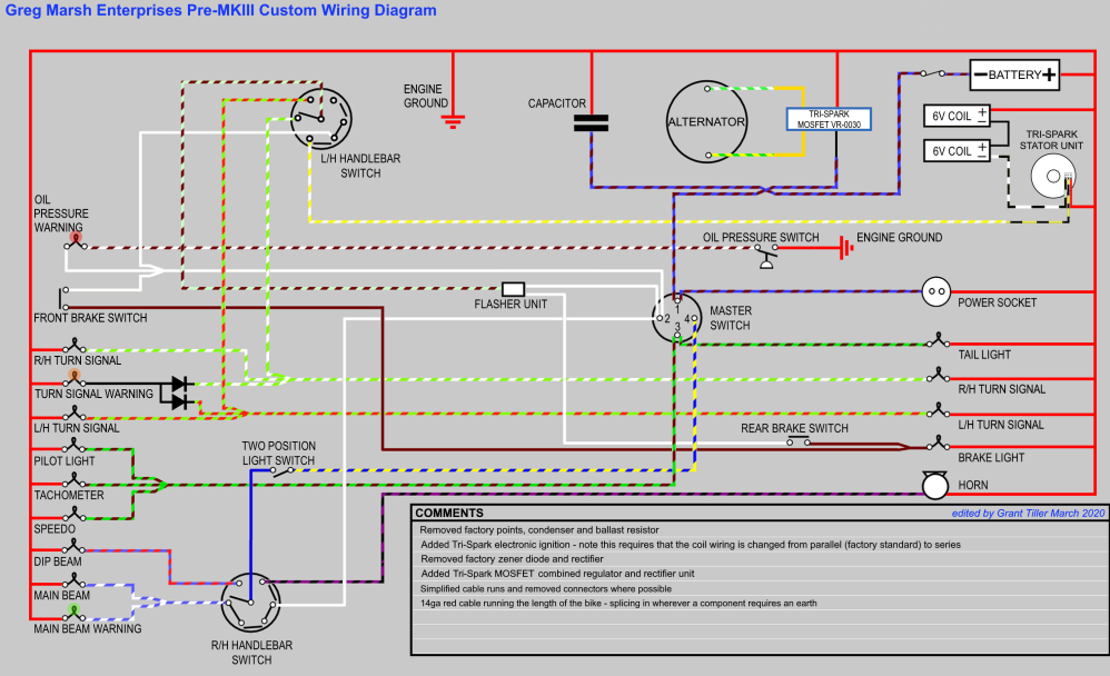
7/27/2020 and then 8/24/2021 I updated the introduction below. Everything from February 25, 2019 down is unchanged
except that I added a wiring
diagram that matches my wiring at the very end of this page.
It might sound strange, but I like wiring Vintage British Motorcycles! But, I also like to update them and eliminate some
of the problem areas and potential for having to push the bike - way too old to be pushing motorcycles!
I already documented the 1972 Norton Commando Combat wiring but several people have asked for details that I didn't
record and I promised to provide more detail on the next one - here it is.
For the bike build itself, look here. Here are the parameters I'll follow:
- Use standard 18ga wire and standard colors. Where there is any deviation, I will spell it out. The modern wire is
the same gauge and same number of strands, but the insulation is thinner so it is easier to run. On most bikes, I
take apart old harnesses and reuse the wire, but almost all Norton wires are short due to the connection under the tank,
so I'll mostly be using new wire. When using old wire it is important to make sure it is flexible along the
entire length. Wire can become "work hardened" and can break at hard spots.
- Replace the points and condensers with a Tri-Spark ignition.
- Replace the Zener Diode and Bridge Rectifier with a Tri-Spark VR-0030 (MOSFET Rectifier/Regulator). I used to use
the PODtronics POD-1P-HP and Tri-Spark noise filter, but the last one I installed caused so much noise that the bike
would not run correctly so I've stopped using them. Today, I use the Tri-Spark MOSFET regulator which has several advantaged
over the PODtronics devices.
- Replace the Warning Light Assimilator with an oil pressure switch that lights the red headlight warning light is the
oil pressure is low.
- Eliminate connectors wherever possible/reasonable. Standard Norton wiring has LOTS of connectors under the tank.
This was done so they could use one rear harness for multiple bikes (standard, police, etc.) The only thing some might
consider good is that reduces the wiring in the headlight shell. It makes handlebar wiring a mess, especially when
changing the size of the bars.
- Normally Nortons use a headlight shell with one wiring hole on the bottom and that will work here as well. I have
headlight shells with three wiring holes on the bottom which makes the wiring a little cleaner so I'll used that.
- The frame is not a part of the ground on a Norton due to the isolastic engine mounts! I modify the rear turn signals
to have a ground wire and I add a ground wire for the taillight. All three connect to a ground wire that runs the
length of the bike - this will become clear later. On other Vintage British bikes, the frame is a good ground so this
is not an issue.
- I use a combination of sleeving, vinyl harness wrap, and heat shrink tubing. The harness wrap is NOT electrical
tape - it has no adhesive and never gets sticky.
- I prefer to have the main run vinyl wrapped and the smaller runs off it in sleeving. It can all be done in vinyl
wrap - many modern cars are that way from the manufacturer. Vinyl wrapping it all is actually easier, but the way
I do it looks better for those wires that can be seen.
Important Notes:
- I buy all my wiring products from British Wiring. I have no
affiliation with them, I'm simply a customer. Throughout this I will provide their part number for each component.
- British Wiring sells wire by the meter and they sell every color needed. I'll attempt to tell you how many meters
of each wire you need.
- In most cases, I connect one end of the wires and run them to the other end without connecting them and I leave them a
little long. Along the way, I tie wrap the harness as I build it. If you try to cut wires to length up front
you will end up to short or long almost every time! Generally, I won't be able to tell you the exact length but
I will tell you how long each wire is when I run it.
- When I do state an exact length, I might change it later - especially for sleeving.
Notice: if you're following along, I made changes to what I wrote 2/25/19 and 3/10/19.
February 25, 2019 Started today. Since the horn is not accessible once the rear fender is installed, that's a good place
to start on the wiring. I cut these:
- Red, 18ga (7/28/19 change: start with one meter, follow what is says below, route the harness to the battery area
and look at the 7/28/19 pictures to see what to do)
- White/Brown, 18ga (7/28/19 change: start with two meters, follow what is says below, route the harness to
the battery area and look at the 7/28/19 pictures to see what to do)
- Purple/Black, 18ga wire. (7/28/19 change: start with two meters, follow what is says below, route the harness
to the battery area and look at the 7/28/19 pictures to see what to do)
- 3mm sleeving 25"
- 3 mm sleeving 6"
- 6mm sleeving 15" (7/27/19 change to 10")
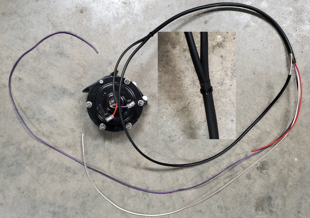
Feed the White/Brown wire through the 25" 3mm sleeving and leave about 2" at one end - this will connect to the oil pressure
switch. the other end will go to the oil pressure light in the headlight.
Feed the Red and Purple/Black wire through the 6" 3mm sleeving and leave about 2" at one end. Terminate those both with
a 1/4" 90 degree female spade terminal and matching cover.
Feed the other end of all three wires through the 10" 6mm sleeving.
Connect the two spade terminals to the horn and adjust the wires in the sleeving to run nicely towards the frame tube next
to the gearbox and temporarily tie wrap it in place.
Connect the White/Brown wire to the oil pressure switch (use whichever connector it requires) and run it along the bottom
frame tube and up to the other two wires.
Now, slide the 6mm sleeving down over the two 3mm sleevings. It will be a little difficult to get them to go it, but
it can be done. Push them in about 1/2". It's not actually required, but I used a small tie wrap over
the junction -
just make it snug. Then run the cable up the frame tube and to the battery area
March 10, 2019 (Updated 7/27/19) Although I like to reduce the number of connectors wherever possible, I changed my
mind and added one for the horn and oil pressure switch. When building a harness, I remove it from the bike several
times as I add wiring sections. When you look at the horn/oil pressure harness in the previous picture, it hs been
changed, but it's too hard to get off the bike for new pictures. There are pictures later, but only of the changes.
Basically, 5" is cut off the sleeving that gos up the frame towards the front of the bike and then the wires are cut
about 1-1/2" from the end of the sleeving and a bullet is put on each. Then the harness is routed to the battery
area - you'll see a picture later. This makes the White/Brown wire too short if you've already cut it.
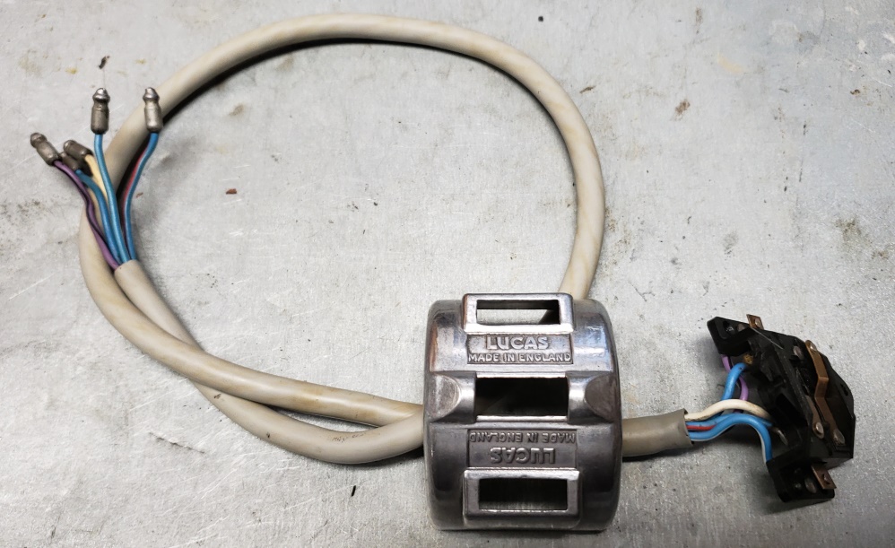
July 18, 2019 I've been of on tangents for a while but this is again my focus. The left handle bar switch console
is restored and installed. The right hand switch console restored and almost ready to be assembled and installed. I'll
polish it a little more and clean the cable a little more as well.
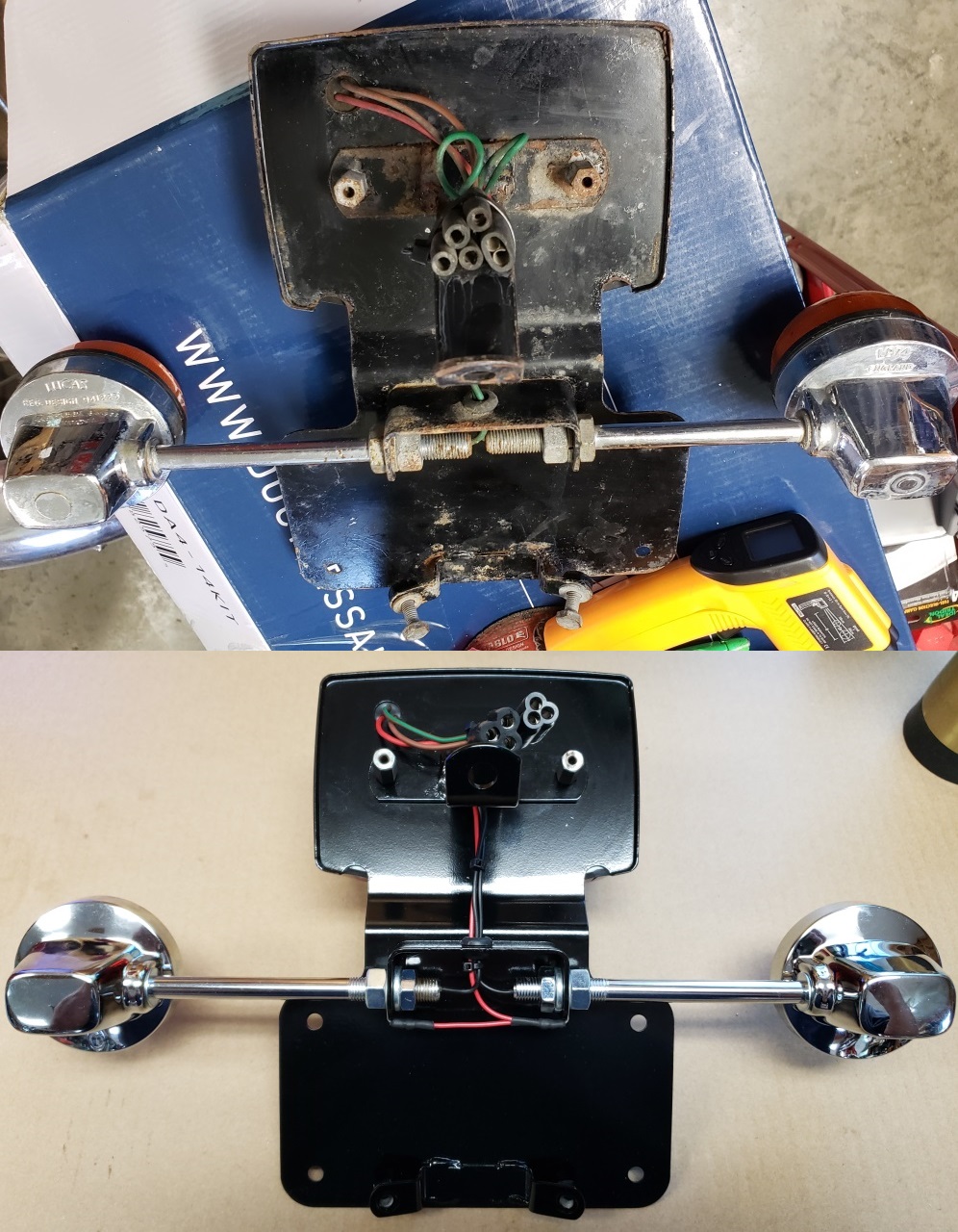
July 21, 2019 Before you can seriously wire the bike, you need the tail light, handlebar switch consoles, and several other
components installed. I already restored and installed the left handlebar switch console. Below is the tail
light assembly before and after. Since I powder coat parts there is no ground to the turn signals and on a Norton,
the frame and fenders are not reliable grounds anyway. So, notice the ground strap I made for the turn signals.
In the past, I soldered a red wire to the socket on the inside of the turn signal, but this is simpler. It's two
3/8" standard eyelets bent to 90 degrees. I used new Lucas turn signals. They are fine except that the
bullets that come on the wires are too small and standard bullets need to be soldered since the wire is too fine to crimp.
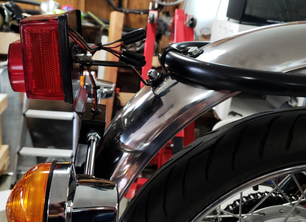
The right-hand switch console and master cylinder are installed and here's the tail light installed. Next I cut
a Green/White and Green/Red wire to 76" and put a bullet on one end of both. I connected the Green/Red to the
left-hand turn signal and the Green/White to the right-hand turn signal. Before running them along the frame, I tested
by connecting 12 volts to the Red turn signal wire and to the Green/Red and then Green/White. I'll include a picture
of them when I add the tail light wires.
July 22, 2019 I cut a Brown and a Brown/Green both to 76", put a bullet on one end of both. Then I made up the
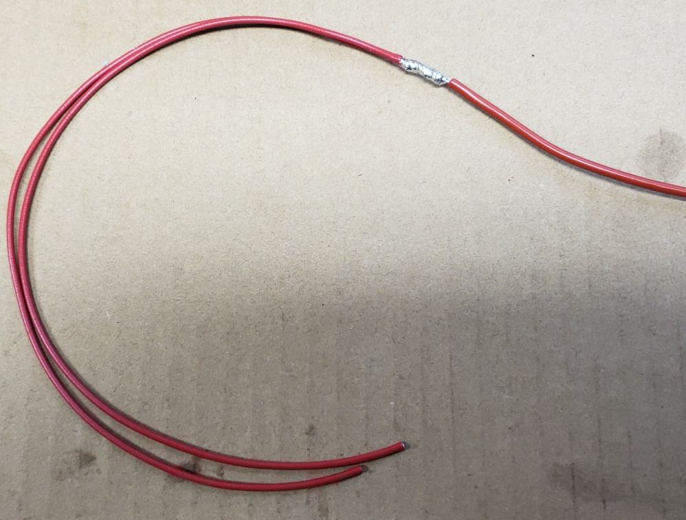
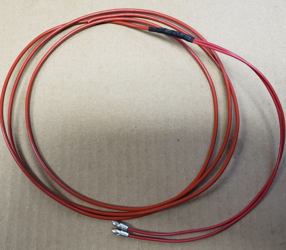
red ground wire. See the pictures below. The mail Red wire that runs the length of the bike is 14ga. I
spliced two 12" 18ga Red wires to the end of a 14ga Red wire and covered it with heat shrink. The 12" is
not critical but I wanted the splice to be in a straight run and 12" works well. I terminated the two 18ga wires
with bullets and the cut the overall length to 76".
Plug in all the wires to the tail light, loosely, figure out the actual routing along the rear frame, and temporarily secure
them to the frame. Then run the unterminated end of the five wires: Green/White, Green/Red, Brown/Green, Brown, and a 14ga
Red and run them to the headlight shell. They pass through the grommets on either side of the oil tank and should
run
on the right side of the steering head and into the center grommet hole in the bottom of the headlight shell. It's tempting
to run the brown wire straight to the front brake switch, but this will lock-in the handlebar size so it's better to
have a cable from the front brake switch to the headlight shell and make the connection there.
July 23, 2019
You can see the capacitor ready to install in the picture below. I normally install them even though it probably would
not work to start a bike with an electronic ignition. It might start with a push start but is very unlikely while
kick starting. It is certainly not a requirement and the bike will run normally without one. Even though it's
not really needed, I use 14ga wire - I don't have Brown/Blue 18ga wire. I have 14 ga and I have the bullets required
for 14ga. You could use 18ga with a Red wire connected to positive and some other color 18ga to negative. The
wires are about 2-1/2" long. With the capacitors I use, the wires must be soldered to the capacitor.
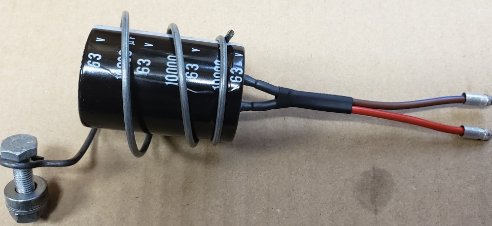
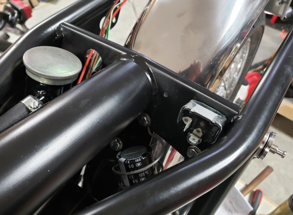
The capacitor and flasher are installed and you can see the wires to the tail light.
Notice: if you're following along, this paragraph was changed 8/3/19.
I also prepared the wires for the Tri-Spark ignition. To do that, I cut a
Black/Yellow wire 43", a Black/White wire 39" and 5mm sleeving to 25". I feed the wires through the
sleeving and left 3: free at one end. The end with the 3" free will go to the points case. The Black/White
wire will go to the negatived of the drive-side coil and the Black/Yellow will go to the headlight shell See the pictures
on 8/3/19 to see how they enter the harness. BTW, if you want a challenge, use 4mm rather than 5mm for these wires
- it can be done, but is very difficult!
July 27, 2019
Prepare these wires:
- Light Green/Brown, 53", install a 90 degree, Female Spade Terminal (C232) on one end.
- Two White wires, one 30" and one 59". Install a Female Spade Terminal (C232) to one end of these wires
(two wires in one terminal)
- Brown wire 54"
- Slide a 15-1/2" piece of 5mm sleeving over the Brown wire and the 30" White wire.
- Slide an 8" piece of 5mm sleeving over theLight Green/Brown,59 White Wire and free end of the Brown wire.
- Splice a 24" white wire to the 59" white wire, 36" from the free end.
- Put a small piece of heat shrink on the free end of the 59" white wire for identification. There will
be two white wires to the master switch. They will both go to the headlight shell, but this one will be lighting and
the other will be ignition.
November 21. 2021 Update: Although there is no specific requirement,
I've changed thew way I do the white wires. I run two from the master switch to the headlight shell and I run one
from the headlight shell to the flasher and then on to the rear brake switch - to this wire I splice a white wire that
goes to the master switch. So, there are three white wires to the master switch. Two in one connector and
one in another. This is done so one wire can feed the left switch console, one can feed the right switch console,
and one runs the turn signals and brake light. In an OEM harness there is one serpentine white wire that runs
everything. That is electrically the same, but when you add the lights, brake light on, turn signals on, and coils
firing via an electronic ignition you are near the capacity of the wire and then you push the horn button and you are over
the capacity.
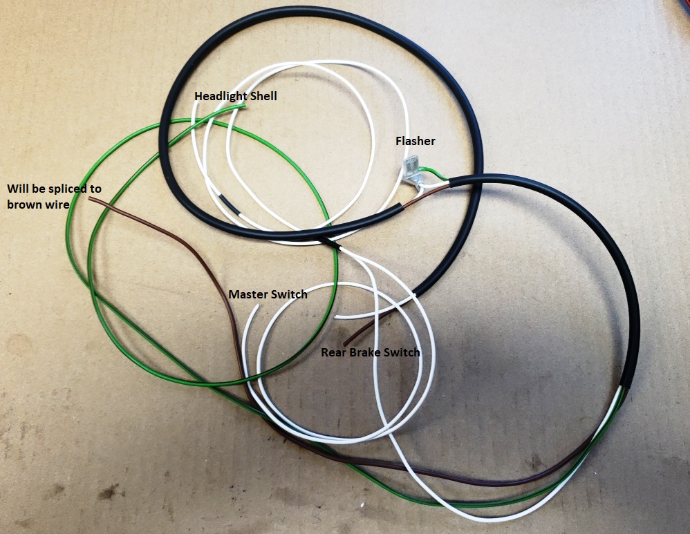
The pictures showing the harness for the rear brake/flasher installed did not come out well. Here's the best one. This
was taken before the sleeving was put on the wires ot the rear brake switch. There will be more pictures of this area
as there are quite a few things more to go here.
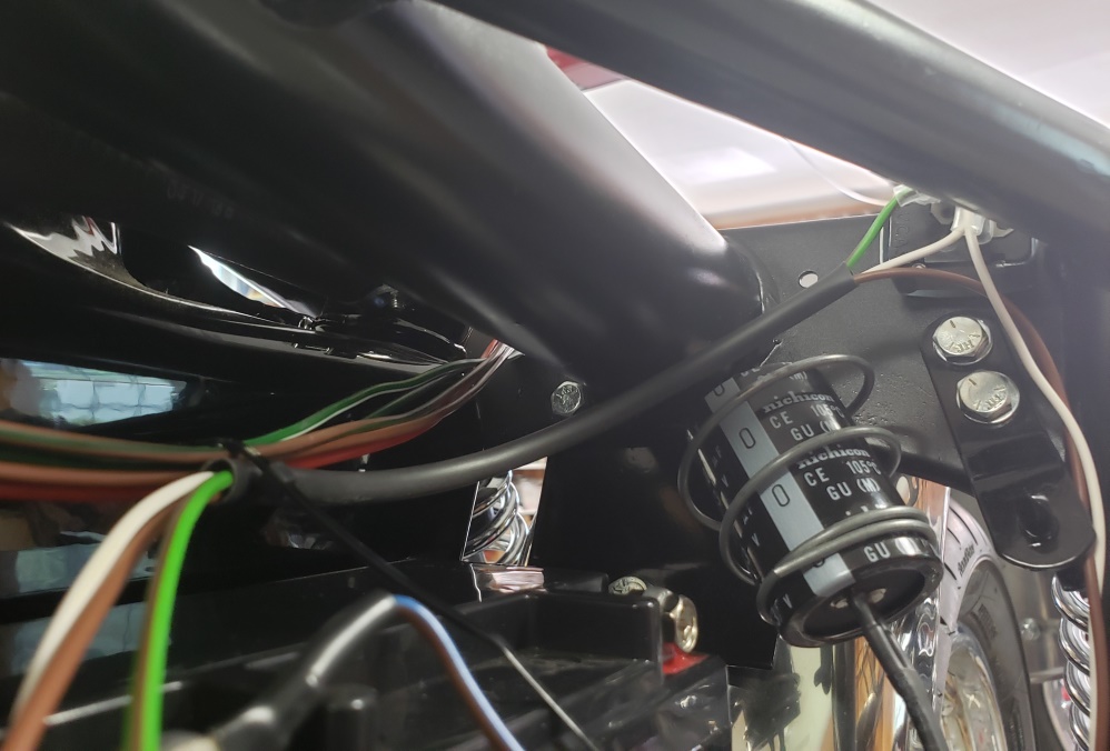
At this point, the main harness needs to come off the bike to install the sleeving for the rear part of the cable,
Cut a 32" piece of 10mm sleeving and slide it over the wires from the headlight end. Leave just enough of the
wires exposed at the tail light end to be able to plug them in. Reinstall the harness and partially plug the tail
light/turn signal wires in (they will need to be unplugged again) and make sure you can fit the tail light housing and that
no wires are exposed. Then firmly tie the rear harness
to the frame. It's important that it's stable as running other wires and splicing need to be in fixed positions.
Cut a a 22" Brown/Green wire and run it form the master switch area and then along the harness - it will be spliced
later.
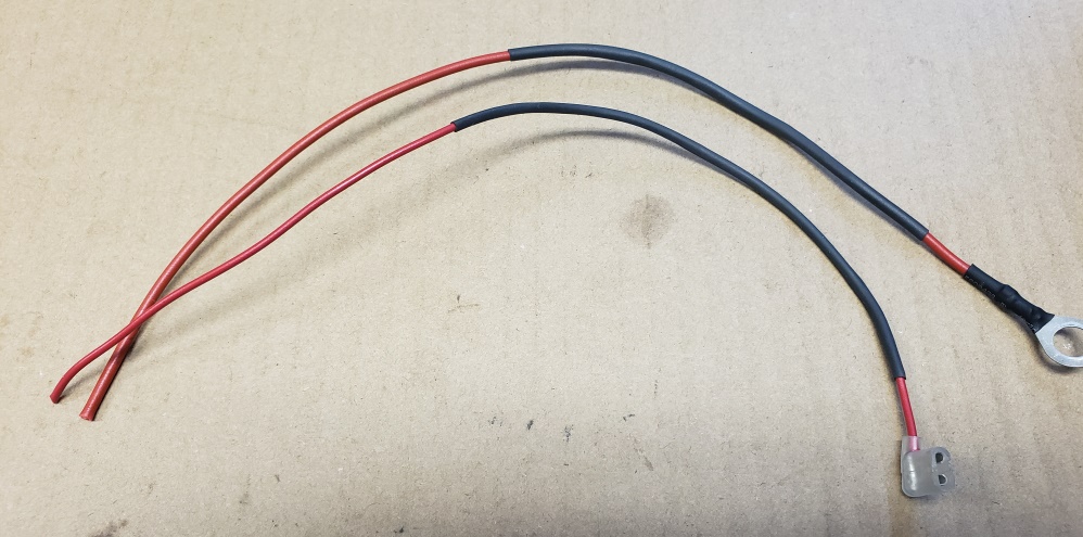
Cut a 13" 18ga Red wire and install a 90 degree Female Spade Terminal (C232) This will connect to the + of the
timing side coil and the free end will be spliced to the 14ga main Red wire.
Cut a 13" 14ga Red wire and install a 5/16" Standard Eyelet (C254). This will be the engine ground.
The sleeving on those two wires if optional. I include it so you don't see Red wires under the tank. I leave
a little Red showing so it's clear that they are ground wires.
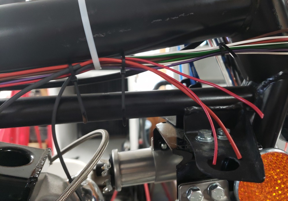
So, here are the last wires to splice under the tank.
There are a few more in the battery area. Once those are in place and firmly zip tied, I'll remove the hardness
again and finish the splicing.
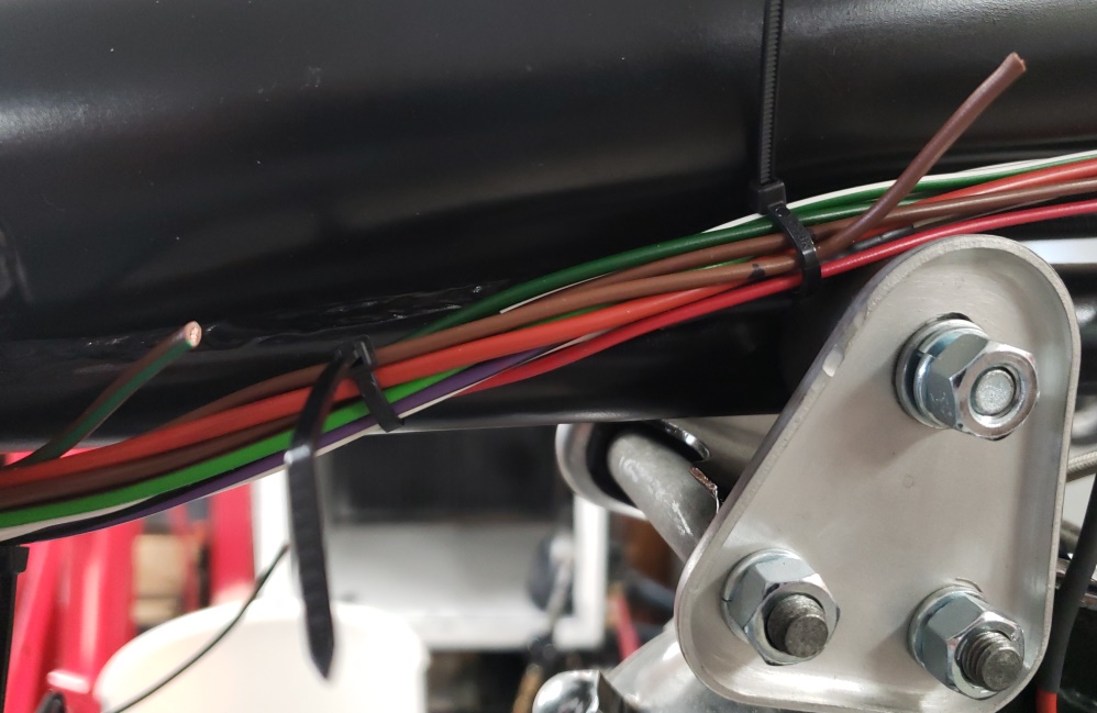
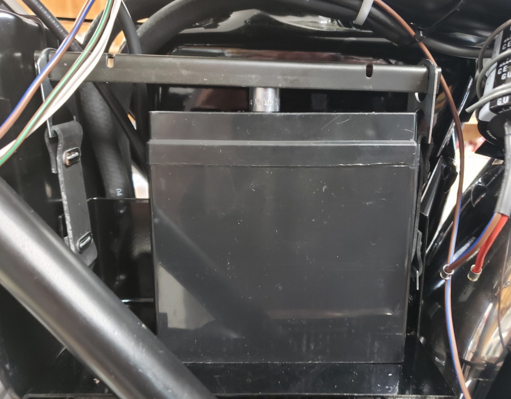
July 29, 2019 In the picture, you can see the problem with the standard battery hold down.
Those are brand new straps and bar. I may use the bottom clips and a rubber strap, or I may do like I did on the 1972
Commando and make a hold down bar. I don't really mind because I like ot install the PODtronics on the back of
the air cleaner. The socket is just there to show how much too high the bar hits! Yes, that's a standard
sized battery.
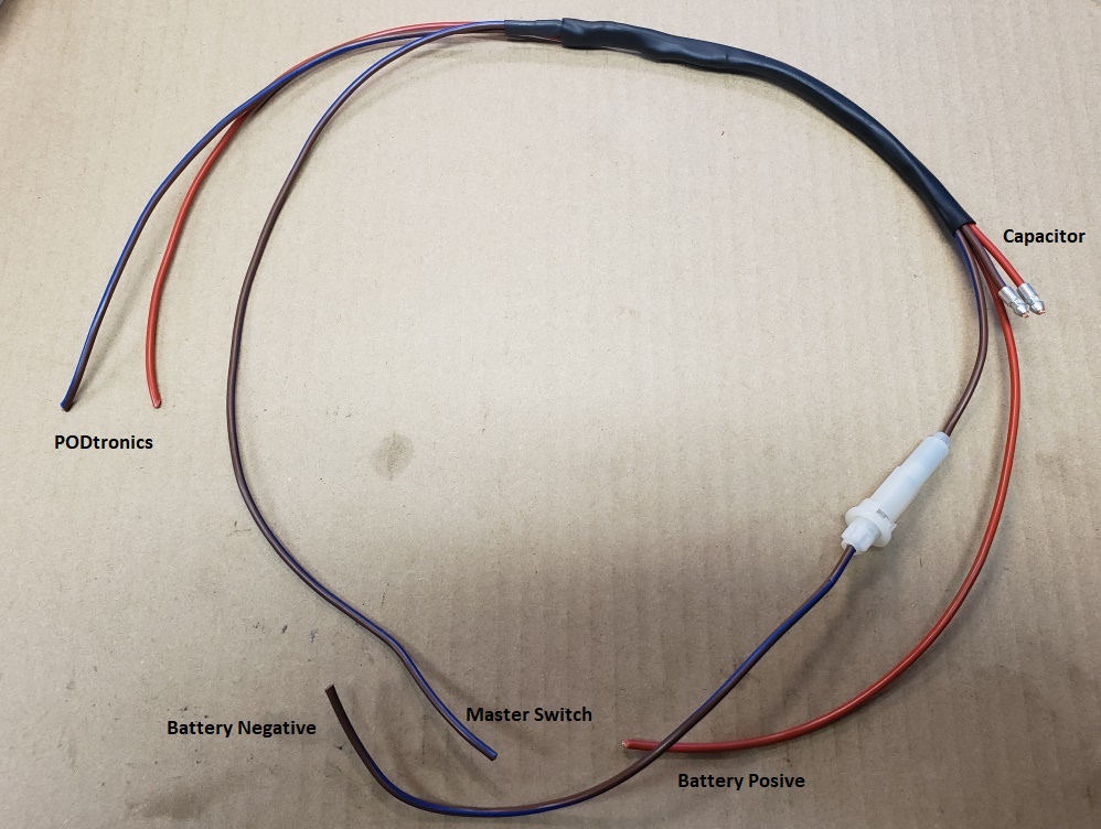
it's time to make the battery wires and get ready to splice them into the main harness. Prepare the following:
- 24" Brown/Blue, 14ga
- 22: Brown/Blue, 14ga
- 9" Brown/Blue, 14ga
- 13-1/2" Red, 14ga
- 15" Red, 14ga
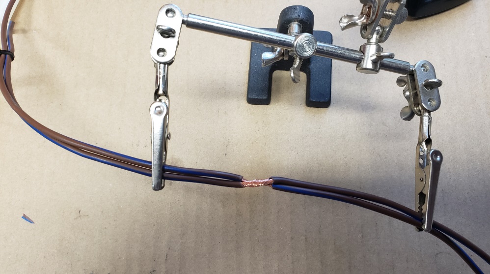
Unfortunately, several of the pictures I took didn't come out usable. The again first one shows how I splice two wires.
Strip (carefully) both wires without cutting the wires, twist them together, and solder. Then cover with a piece
of heat shrink followed by another piece a little longer. Before splicing, secure the wires so the right end of the
22" wire's end is 2" to the left of the 24" wire. Remove the insulation on both wires after measuring
11" from the right end of the 24" wire.
The Red wires are done a little different. line up the 13-1/2" Red wire with right end of the 22" Brown/Blue
wire. Line up the 15" Red wire with the left end of shorter Brown/Blue wire. See the finished picture.
Splice the two red wires together.
Install a bullet on the Red and Brown/Blue wires on the right that are lined up. Install the large part of the fuse
holder on the long Brown/Blue wire on the right. Install the other end of the fuse holder on the 9: Brown/Blue wire.
In stall a fuse to hold them together.
Slip either a 7", 10mm sleeving or a 7" 10 or 12mm heat shrink tubing. The wires are left longer than needed
on purpose - once added to the main harness they will be shortened and terminated.
Note: if you are going to mount your PODtronics in a different place or you are going to use a different
battery, you might need to adjust. Also, if you're not going to install the capacitor, yow don;t need the shorted
Red and Brown/Blue wires on the right.
August 3, 2019 After
a miserable week in my real work, I'm back to wiring this Norton.
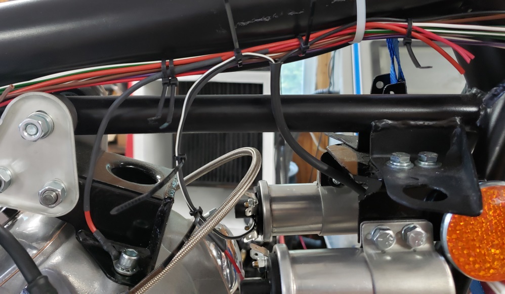
I changed my mind on the ignition wires and will make them a part of the main harness. With Tri-Spark, the Black/White
wire goes to the negative of one of the coils and the Black/Yellow goes to the ignition switch (through the kill switch).
The picture shows that in place.
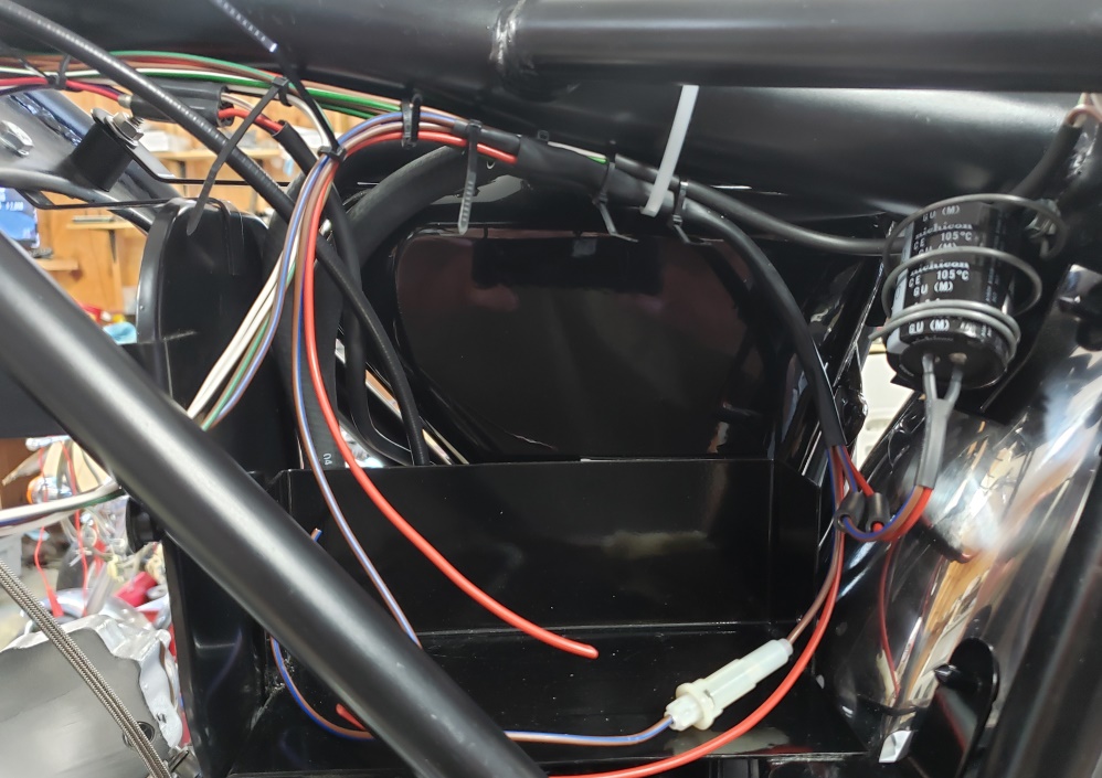
Next, the battery sub-hardness needs to be positioned. Then the position of everything is checked. Only minor
changes will be possible after the next steps. While installing this, I noticed that I had forgotten the Blue/Yellow
wire form the master switch to the headlight switch, so I added that. I had a 1 meter piece so I didn't cut it.
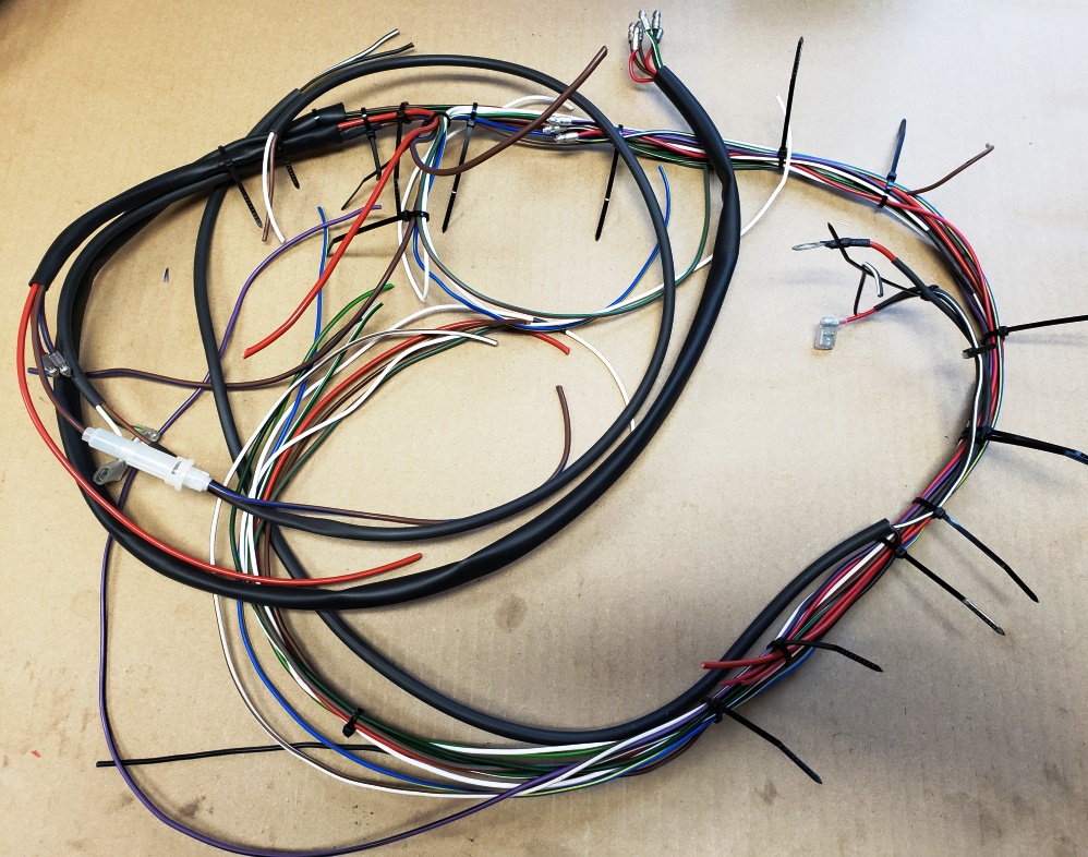
Here's the harness off the bike ready for the last few splices to be made. Notice that there are many zip ties
to keep everything in place.
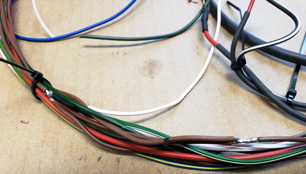
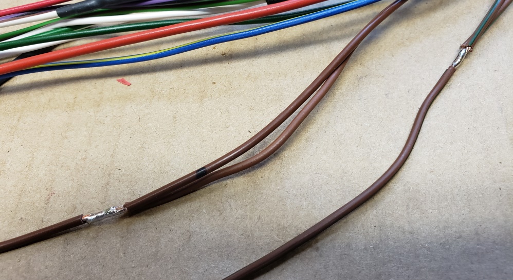
First, the free Brown wire needs to be spliced to the Brown wire that runs the length of the bike. Similarly, the
Brown/Green wire needs to be spliced to the Brown/Green wire that runs the length of the bike. The heat shrink will
have to go on after the Red wires are spliced - don' want to disturb the location of the Red wires right now.
The next three pictures show the Red wires being spliced. I forgot to take a picture of the last splice :-(, but as
you can guess, the remaining free Red wire is spliced to the Red wire that runs the length of the bike.
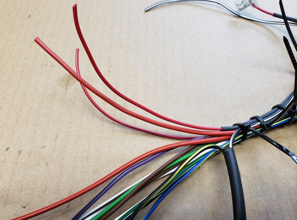
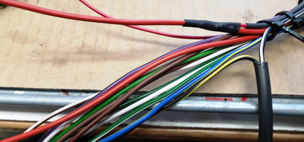
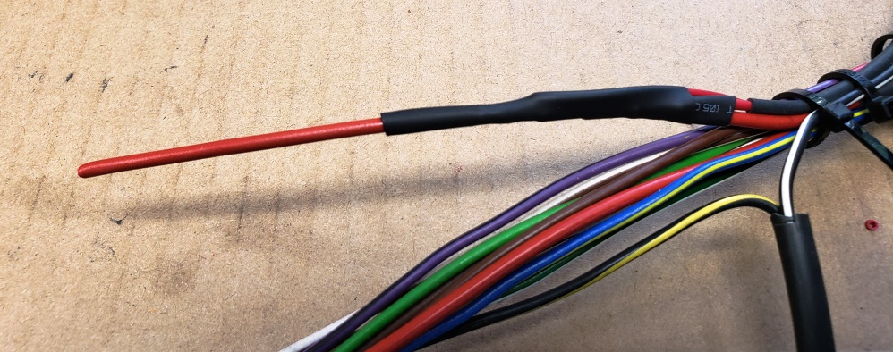
Once the Red wires are all spliced, the zip ties can be removed to expose the Brown and Brown/Green wires so that heat shrink
can be applied. Of course, I forgot to take the after picture!
Here's the harness back on the bike and carefully aligned. Where there are two zip ties together it means that
the wires will exit the harness at that point. It's important that everything be properly located at this point
because we need to install the battery connections, master switch, and headlight switch so we can test everything before
finalizing the hardness. It's very easy to forget a needed wire and a royal pain to have to go back and add it
once the harness is wrapped - been there, done that, didn't like it!
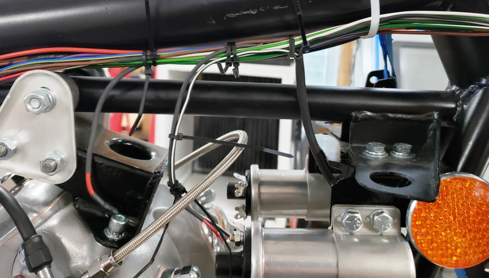
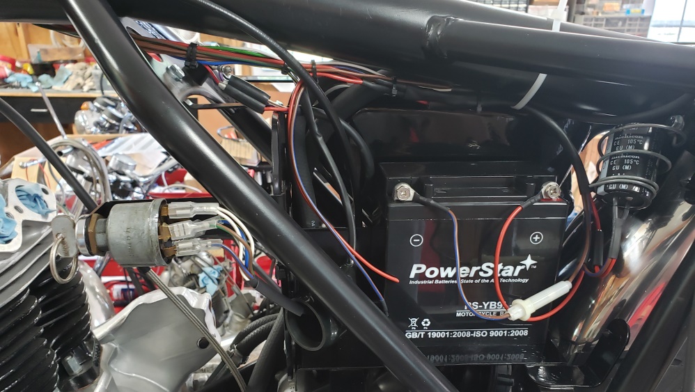
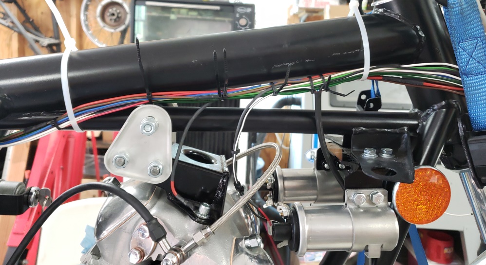
August 6, 2019 In fact, all tests failed! When I installed the battery sub-hardness, I forgot to splice the Red wires!
Here it is with that resolved and back on the bike. This time, every circuit checked out. Note that each connector
was only partly pushed on. Especially spade connectors should be put on and taken of as little as possible Also,
that master switch didn't work and I took it apart and fixed it but I'll test is a lot more before committing to
it. I did not completely wire the bike this time - the wires in the headlight are all unterminated. I simulated
them being connected to be sure things worked.
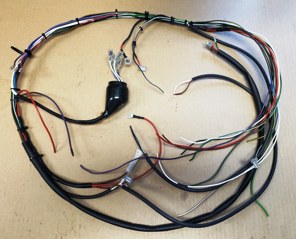
Once the testing is complete it's time to triple check the location of all breakouts from the harness and to add enough
zip ties so the harness more or less holds it shape while wrapping. Here's it is, ready to be wrapped.
Here I've just started wrapping. That is NOT tape - there is no sticky side! It is vinyl wrap made for harnesses. I
wrapped in place 3 wraps to give extra strength to the end of the wrapping and then started down the harness. I like to
overlay each wrap by about one half the width of the vinyl wrap. When wrapping you pull it snug but not enough to stretch
the wrap.
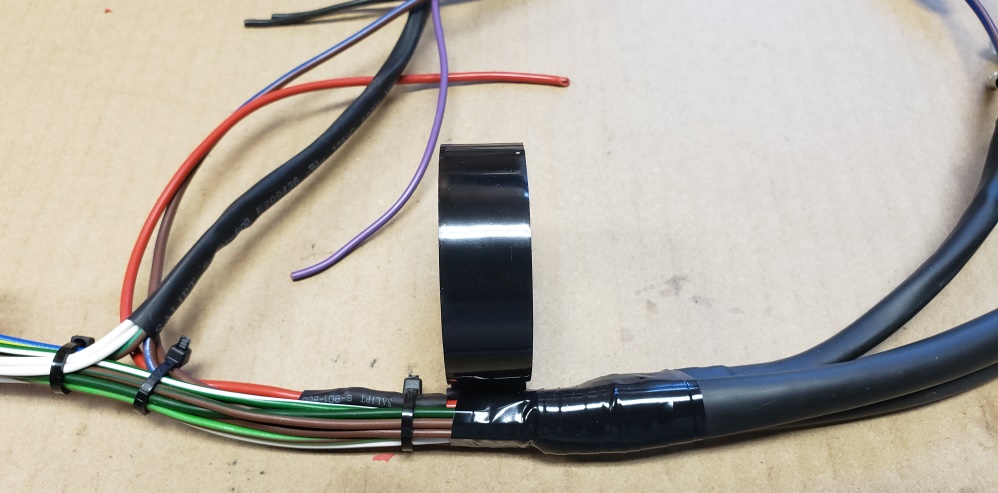
Here the wrapping is complete. I chose to end the wrap short of the headlight shell - in the second picture you'll see
a 8" piece of 14mm sleeving that will enter the headlight and cover well back on the harness just like the original
harnesses.
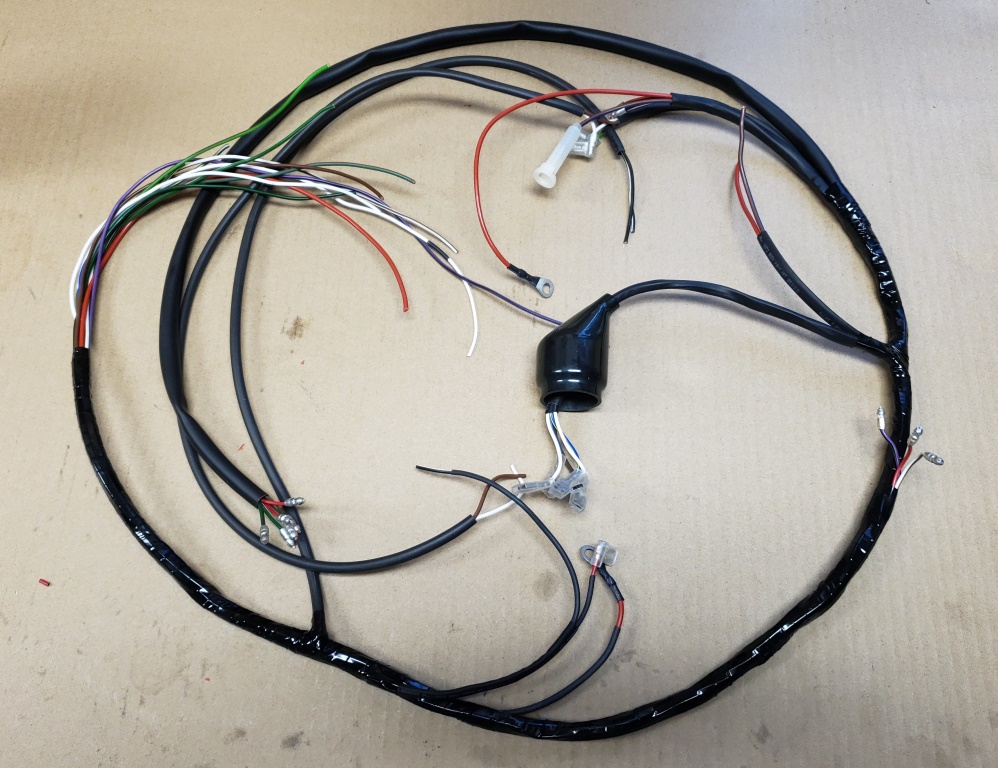
The harness is installed and ready for the final wiring.
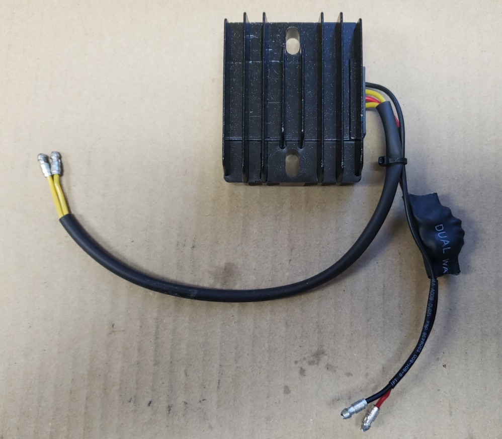
August 9, 2019 Here's the PODtronics-1P-HP ready to install. The device to the right is a noise filter.
Tri-Spark found that this version of the PODtronics causes misfiring at 3-5000 rpm due to electrical noise. The device
is connected to the Red wire from the PODtronics and the other end goes to ground.
I also terminated the rear brake switch wires with two right-angle spade connectors and covers and the Blue/Yellow wires
with another one that connects to the headlight switch.
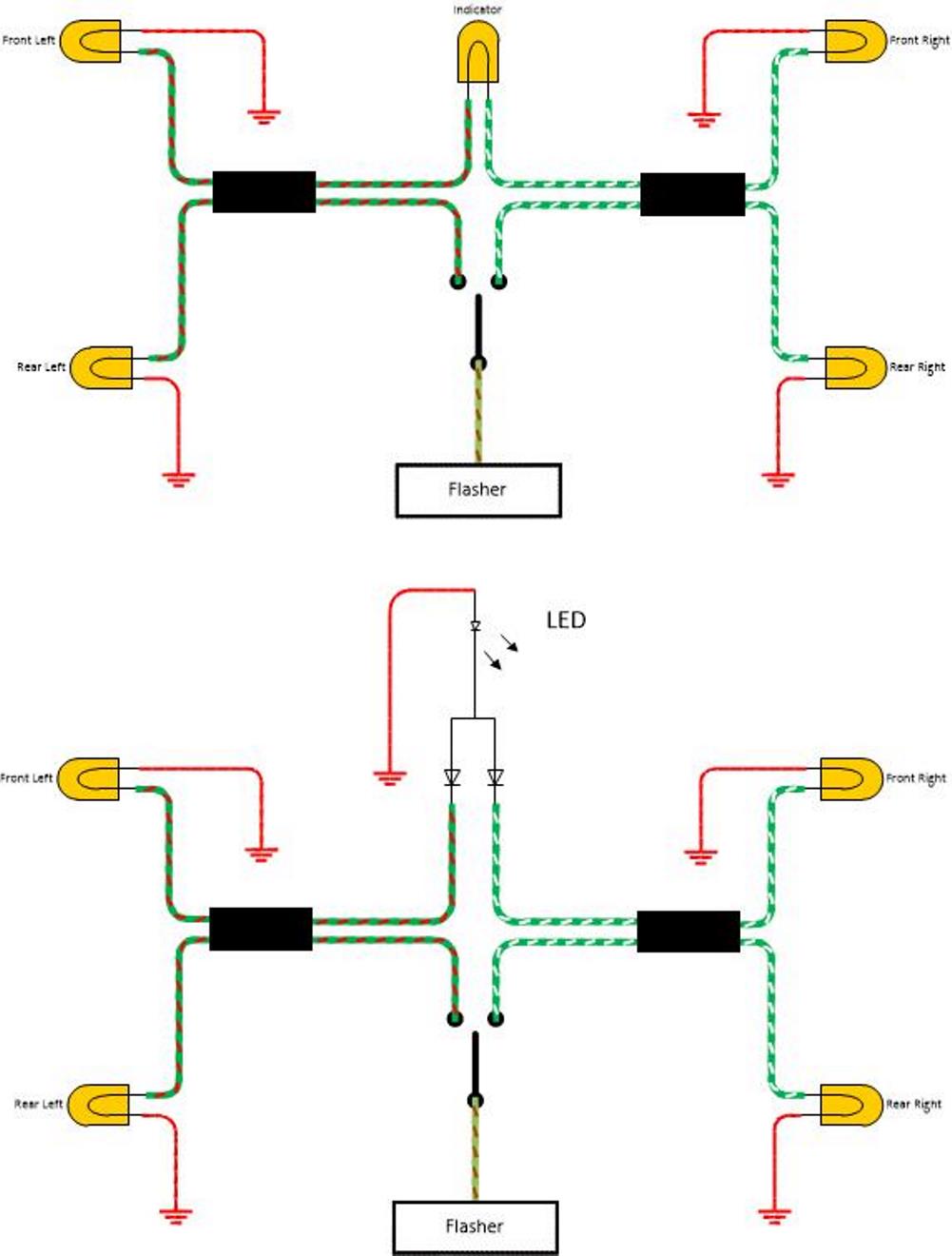
August 10, 2019 I like to use LEDs for the headlight warning lights. They are readily available in the correct
base, but are negative ground. That's fine for the currently available warning lights from Lucas since the wires
connect by spade terminals. However, they won't work for the turn signal indicator. That's because the
indicator gets
it's ground from the turn signal that is not on - in other words, the current flow is reversed when switching between
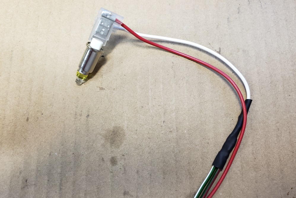
left and right. To fix that, two diodes are required. I happened to have 1N914 diodes so I used them, but any
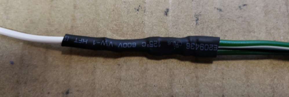
small standard diode would work. The next 5 pictures show the cable with diodes being built and then installed to
the socket. Notice that the Red (ground) wire goes to the center connector since we are positive ground.
Of course, if you are using the standard bulbs, you don't need the diodes!


Here's a schematic showing the standard wiring (top) and the modified wiring.
August 19, 2019 Been off doing other things, but I'm
back on it now. The Tri-Spark ignition is installed, tested, and statically timed.
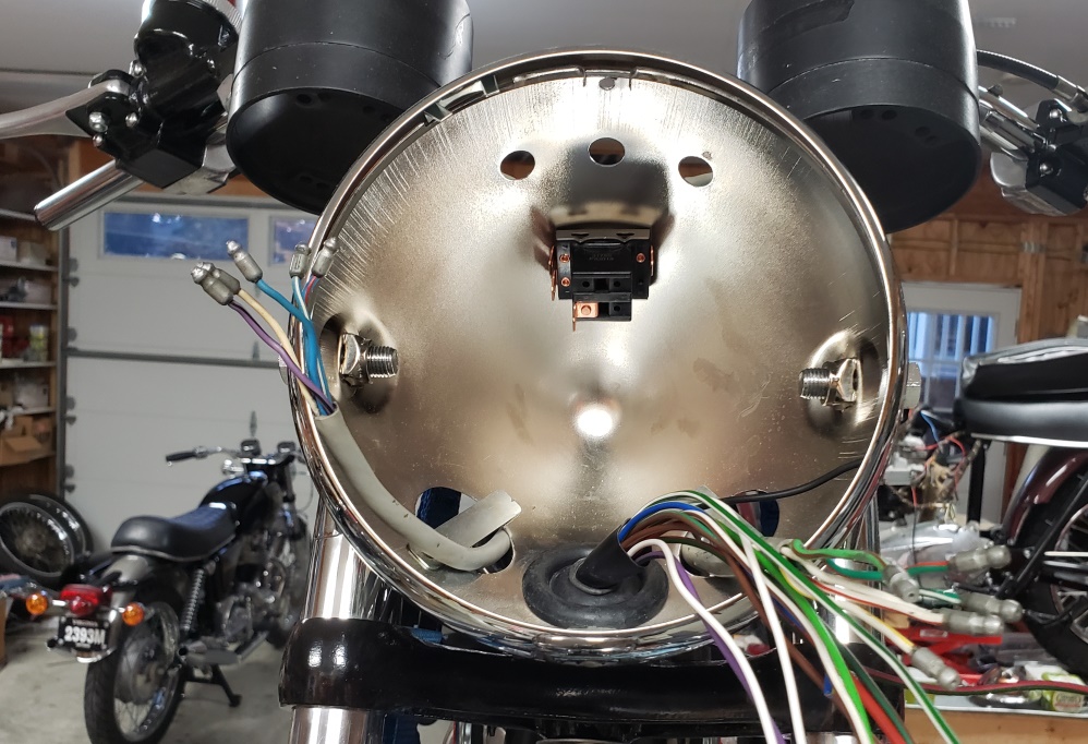
A little more wiring and I'll show the inside off the headlight shell. It's best to form all the wires to
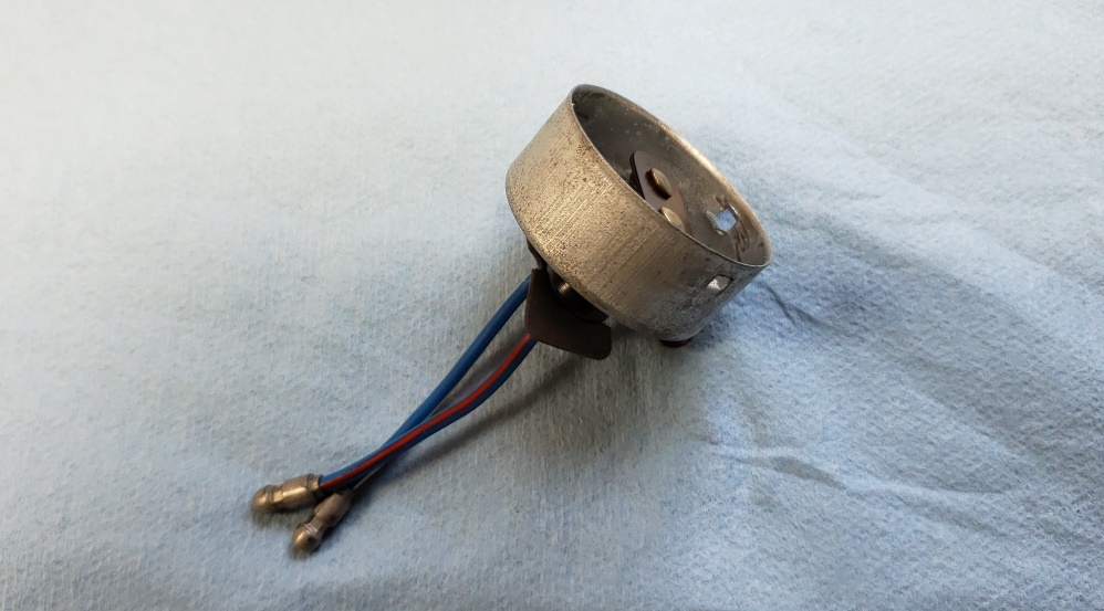
the back of the shell to make it easier to get everything in. I'm using a British Pre-Focus (BPF) positive ground
LED. This wiring would be the same for a standard bulb. The BPF socket is shown below. Notice the short
wires - that's standard on Norton, Triumph and BSA. However, it is difficult to route all the wires with those
short wires. So, as shown they are 2-1/2" long and I extend them to 6-1/2". This allows them to lay
in the back of the headlight shell without disturbing other wires. It's not really required, just something
I prefer.
All wiring is complete except the speedometer and tach illumination.
August 20, 2019
Fortunately, the donor bike came with two good instrument harnesses. They were covered with tape and dirt. This
is the kind you want if you'll use LEDs for the speedo and tach. The metal tangs that hold them in the instruments
are not connected to either lead - it they were, it would not be possible to use LEDs. I toyed with the idea of spicing
them inside the cover so red could go to ground, but decided to just reverse the wires inside the headlight shell.
The LEDs shown greatly improve the lighting of the instruments. Since these normally connect under the tank, they
are too long so I need to shorten them.
So far you need:
- Red, 18ga, 2 meters, (C114)
- Red, 14ga, 3 meters, (C128)
- White/Brown, 18ga, 2 meters (C114)
- Purple/Black, 18ga, 2 meters (C114)
- Green/Red, 18ga, 2 meters (C114)
- Green/White, 18ga, 2 meters (C114)
- Brown, 18ga, 3 meters (C114)
- Brown/Green, 18ga, 3 meters (C114)
- Brown/Blue, 14ga, 1 meter (C128)
- Black/White, 18ga, 1 meter (C114)
- Black/Yellow, 18ga, 2 meters (C114)
- Blue/Yellow, 18ga, 1 meter (C114)
- Light Green/Brown, 18ga 1 meter (C114)
- White Wire, 18ga, 3 meters (C114)
- 3mm sleeving, 1 meter, (C703)
- 5mm sleeving, 2 meters, (C705)
- 6mm sleeving, 1 meter, (C706)
- 8mm sleeving, 1 meter, (C708)
- 10mm sleeving, 1 meter, (C710)
- 14mm sleeving, 1 meter, (C714)
- 1/4", 90 degree, Female Spade Terminal, 14, (C232)
- 1/4", 90 degree, Female Spade Terminal cover, 14, (C233)
- 3/8" Standard Eyelet, 2, (C255)
- 5/16" Standard Eyelet, 1, (C254)
- Isolated Triple Bullet Snap Connector Sleeve, 3, (C333) (Optional, could use Single Sleeve Snap Connector, 9, (C311)
which would save about $9.00)
- 10,000uF electrolytic capacitor, 63 volt, Optional
- Crimping Bullet for 14 Strand PVC Wire, 24 (so far) (C314)
- Crimping Bullet for 28 Strand PVC Wire, 4 (so far), (C324)
- Amber Warning Light and Amber LED (optional, can use white LED or normal bulb)
- Red Warning Light and Red LED (optional, can use white LED or normal bulb)
- Green Warning Light and Green LED (optional, can use white LED or normal bulb)
7/27/20 Wiring diagram. For a larger view: Norton Wiring
|