Home
Motorcycle Home
Triumph Home
Export Home
Norton Info Home
Special Parts
Updated
01/29/26
Master Switch Bracket
Updated
01/29/26
MKIII Rebuild
Updated
01/29/26
Combat 5
Updated
02/01/26
High Mileage Combat
Updated
02/18/26
Roadster 850
Updated
01/29/26
Customer Combat
Partial Rebuild July 24
Delivered 03/22/25
850 Commando
Recommission
Delivered 09/20/24
Customer Combat
Build Oct 23
Shipped 7/13/24
1975 Norton Wiring
Delivered 06/07/24
Blue 69S
Delivered 05/17/24
High Mileage 850
Delivered 03/26/24
Mk3 Engine & Gearbox
Delivered 03/07/23
1973 Customer
BasketCase Build
Delivered 07/15/22
1974 Norton 850
Commando Rebuild
Sold 01/12/21
Updated 06/10/21
Customer Combat
Delivered 09/07/20
First Place Norton 05/18/2025
1972 Norton 750
Commando Rebuild
Completed 05/15/19
First Place Norton 05/16/19
Sold 01/01/20
1972 Norton Wiring
Completed 07/19/18
1974 Norton Wiring
Completed 07/27/20
Customer Combat
and 69S Builds
Closed 10/18/23
|
 | Thursday, February 19, 2026 |
In 2019 I was contacted by a guy building a 1972 Norton Commando Combat. His goal
was to get the bike on wheels and complete
and then bring it to me to finish and that's what he did. The engine/gearbox were
of unknown condition and the cylinder
head had broken fins and had been painted black (poorly). Also, the bike was built
on a 850 frame that had holes in strange
places, a broken steering stop, and the front end assembled very wrong.
He had a 750 frame at home and he found a really good deal on getting frames powder
coated. At the same time, I had
a Combat apart in boxes. So we decided to have both of our frames powder coated
which meant for the second time this year,
I started a frame swap. Since I was in a hurry to get his bike apart, I didn't
take pictures.
So far: His replacement head is ready to go. That actually shocked me! The replacement
head he bought had no valves or rockers
and was a little dirty. I cleaned it up without doing my normal beatification. I
took the valves from his old head, protected
the stems with tape and media blasted them. The two intake valves lapped in fine!
One exhaust valve guide was bad so I had
to change it � then that valve lapped in fine without cutting the seat - unheard
of! The other exhaust valve lapped OK but
on close inspection the surface was pitted so I stripped a valve from another old
Combat head and it lapped in fine. On
that last exhaust valve I noticed that the guide was wrong � no place for the insulator
and spring seat. I didn't have
another
guide to I took the one from the head where I got the valve � used lots of heat
so I wouldn't damage the guide on the
way
out. You guessed it, the valve lapped in fine. All the rocker gear from the original
head was fine and is now installed
in
the replacement head.
May 14, 2020 He picked up the frames to take to the powder coater.
May 15, 2020 I've decided to document this one since he doesn't want my
normal "make it look new". Today,
I took the crankshaft apart to check the journals and clean the sludge trap. At
first glance, the sludge trap was almost
clean. Unfortunately, all the nuts were staked so a new bolt set is required. On
closer inspection as I cleaned everything
I found tiny flecks of silver, shiny metal everywhere. On careful inspection the
journals are fine but would not have been
for long. The bearing shells have embedded flecks of brass or bronze and some minor
scoring so they will be replaced as
well.
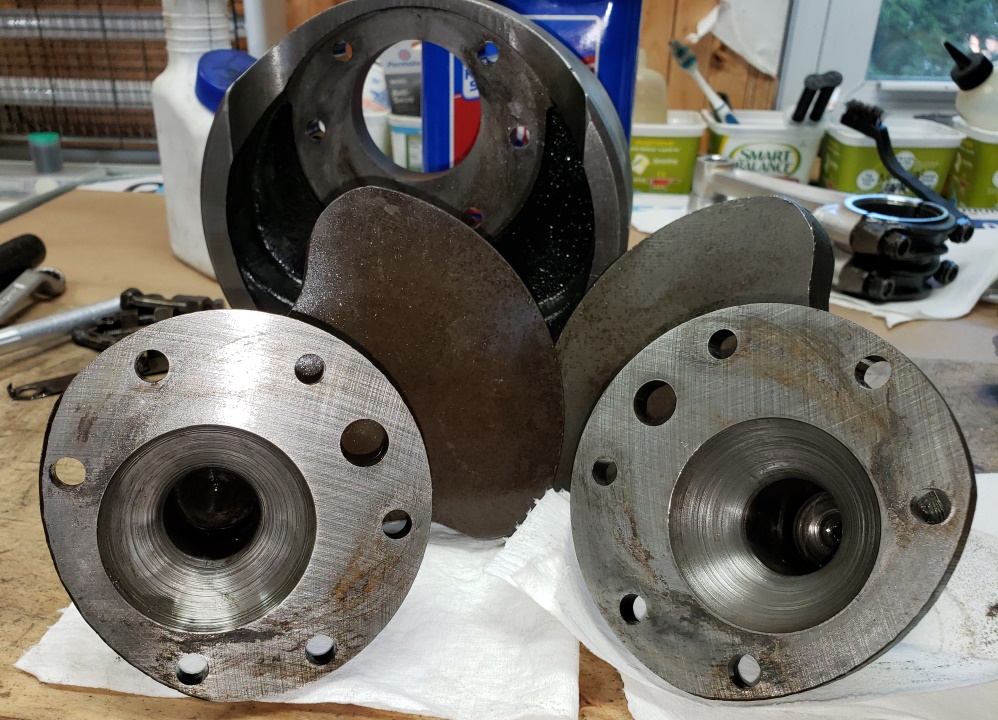
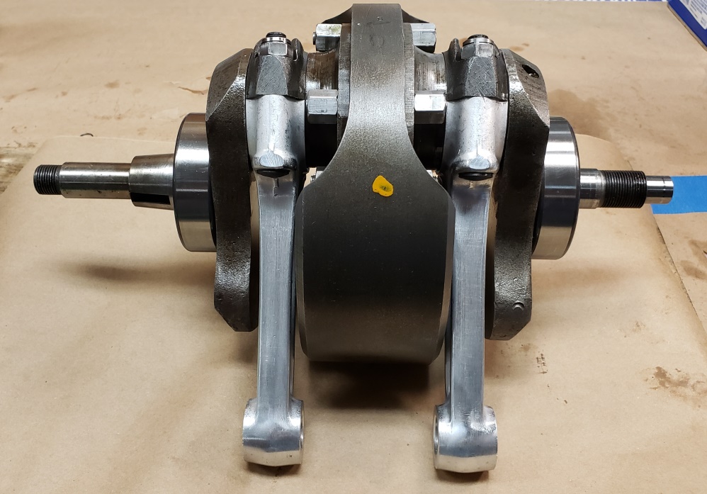
May 16, 2020 The crankshaft is ready to go in the cases. It has a new bolt set,
new big end shells (standard size), new
conrod bolt nuts, and new "SuperBlend" bearings. I keep the bearings together
until I put the outers in the case.
The bottom end should be together and in the engine stand tomorrow.
May 17, 2020 Today started with a simple goal that should have taken 1-2 hours -
get the crankshaft and camshaft in the
cases and get the cases mounted in the engine stand. Things didn't go well!.
First problem: Whoever worked on this engine last used some sort of permanent, hardening,
gasket cement on all mating surfaces.
I tried every chemical I had to soften it. I ended up carefully removing it with
single edged razor blades � took over
three hours!
The camshaft on this engine used the tab thrust washers that are notorious for destroying
engines. Most people just cut
the tabs off so they cannot break off and damage the engine. But that means that
the thrust wasters are free to spin with
the camshaft and that seems like a bad idea since the aluminum engine cases would
be the real thrust washers then. I had
the more modern bushing in stock that eliminated the need for the tab washers, but
you need a camshaft with oil grooves.
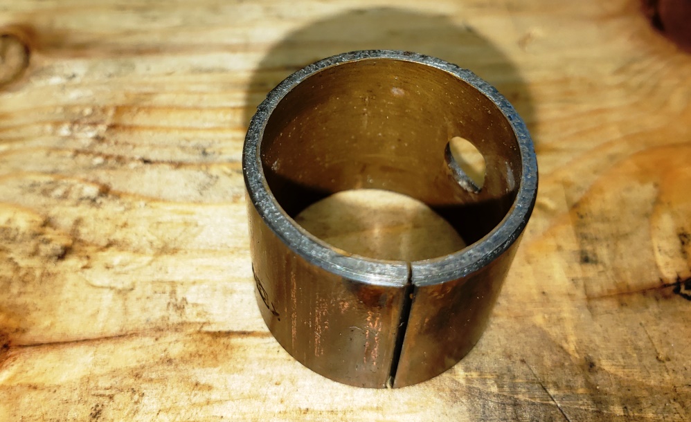
Upon close inspection, I realize the bushing in the engine was the rare type that
had no groves in it. So the bushing wasn't
grooved and the camshaft wasn't grooved. So, at a minimum that bushing had
to be replaced. Since I was going to replace
the bushing and I had the newer style and not the original style, I decided to use
the newer style. Then I looked at the
new camshaft I had for another engine I'm building and realized that it's
a modern Combat (2S) camshaft with the
oil grooves.
So, I installed the new bushing and will use the new camshaft � I'll get the
other one grooved later.
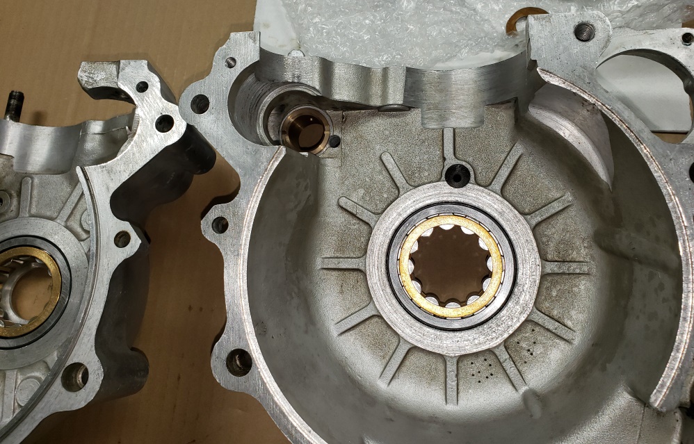
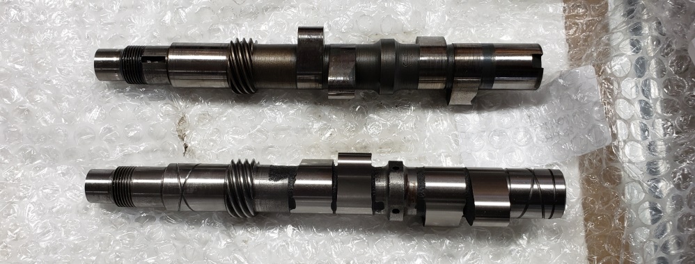
The three pictures show the removed bushing, the new bushing and Superblend bearings
installed, and the two camshafts discussed.
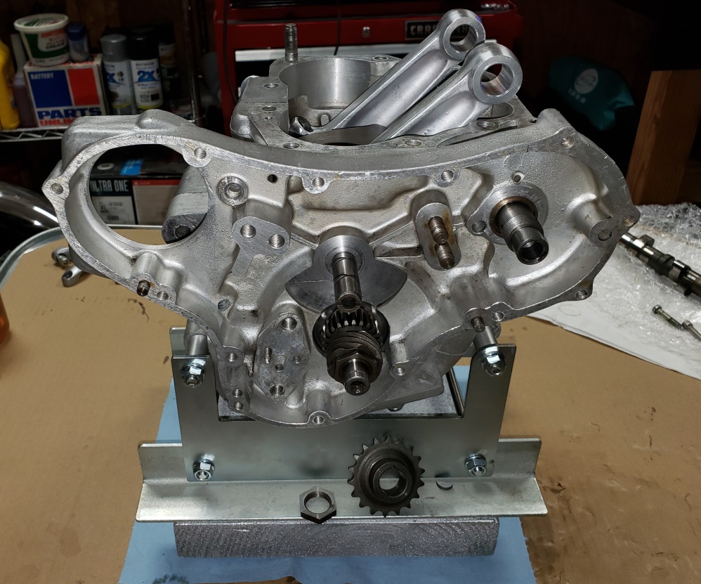
May 18, 2020 Putting the crankcases took a while! The camshaft bushing was perfectly
sized to the camshaft when I installed
it, but it shrunk a few thousandths once installed. It took very careful reaming
so not only fit it, but align with the
opposite bushing. At any rate, its together now and everything is very smooth.
May 19, 2020 Finished the timing side of the engine except the oil pump.
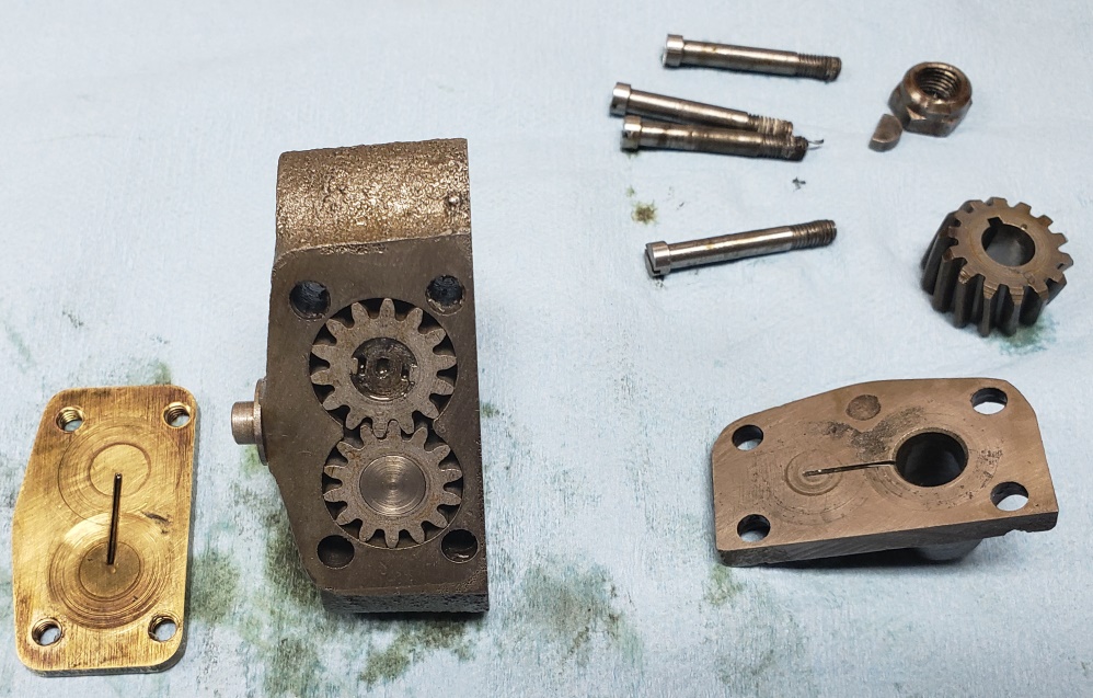
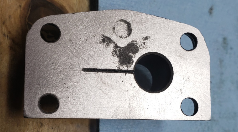
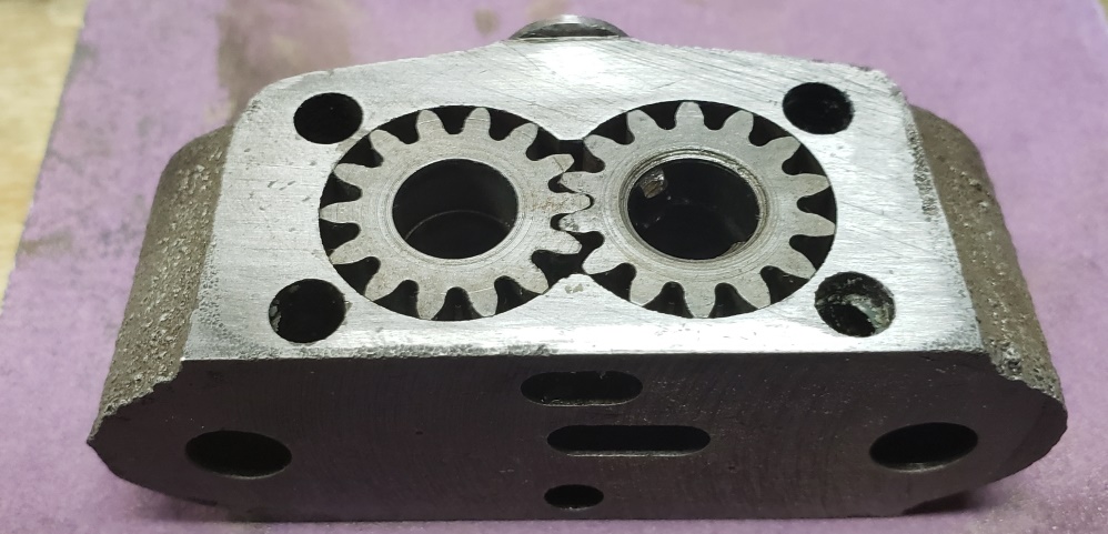
The next five pictures show the work done to the oil pump. Norton oil pumps are
notorious for allowing oil from the tank
to seep past the pump and fill the crankcase when the bike sits (wet sumping). This
can be improved by reducing the clearances
in the pump, especially on the feed side (thin gears).
The first picture shows the bottom cover (on left) and scoring. It also show the
top cover with some scoring and a manufacturing
defect.
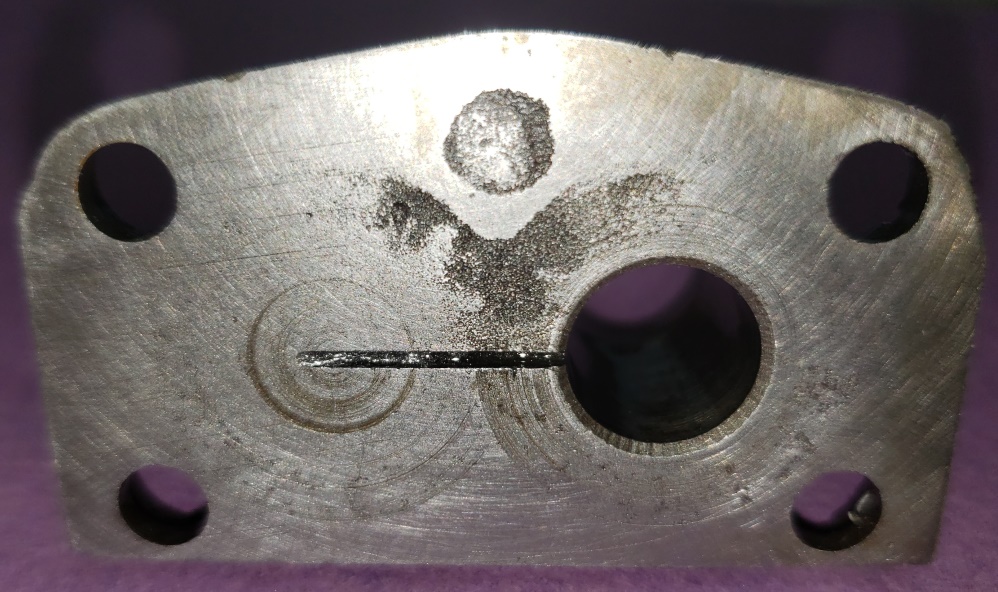
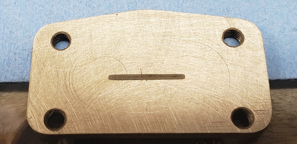
The second and third pictures show those covers before and after dressing. The
dark pitted looking areas are actually a
manufacturing defect � the casting was not good and the milling did not cut out
all the bad area. I have reduced it to
a point where I'm sure it will be OK. Fortunately, this is the return side
of the pump and can't contribute to
wet sumping
and since the sealing surface is fine outside the gear area it will be efficient.
This needs to be the last time this pump
is refurbished.
The forth picture shows the bottom cover dressed. Usually, this is all people do
but I take it a couple of steps more.
With the gears in place, I dress the bottom side just until I start to see the gears
being rubbed. The goal is to get to
zero clearance without binding. I also lightly do the top side.
Then I carefully clean everything, including the slot in the top and bottom, and
then assemble but only lightly tightening
the screws. Add some oil to each port and feel how the pump turns. There must
be no binding, but there should be some
resistance.
Once I'm happy, I take it all back apart, re-clean everything, and put it back
together using Loctite on the screws
and
tightening well.
May 20, 2020 I must not be living right! I got the timing side all together and
then got the timing cover out to install.
What was sitting in the cover � the oil pump! That's right, the oil pump that
I got ready yesterday was one I had lying
around and I thought it was the one for this bike. I thought about continuing but
decided to refresh the one that came
wih the bike � it ended up being much better than the one I did yesterday so I installed
it.
Then I started cleaning up the timing cover. Besides the two seals that must be
replaced, it is important to remove the
pressure relief valve to clean and inspect it and to make sure all the passageways
are clear. Well, the last person to
work on it was a gorilla! After an hour of trying, including with heat, I finally
got the cap to come loose. On inspecting,
the piston was stuck. A lot more time fiddling and I finally get the piston out.
Then I started again trying to get the
body out. Two flats on the hex were destroyed � have no idea how someone did that.
I finally got it out what an air impact
gun. At a minimum, the body must be replaced.
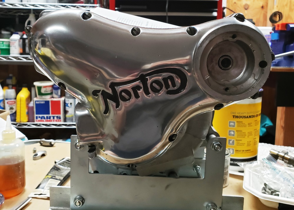
I spent a while at the buffer making the cover look decent. It has some nicks and
scratches that could be removed, but
the owner doesn't what the new look so I just polished it enough to look like
a decent rider. I hope to finish the
timing
side tomorrow and start on the gearbox. Hopefully I can restore the cradle this
weekend install the engine and gearbox
so I can start on the primary.
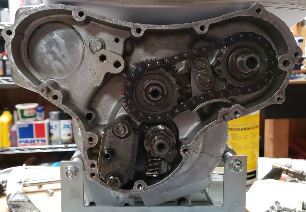
May 21, 2020 I would really like to talk to the idiot who last worked on this engine!
I spent over an hour getting the
old gasket/cement off the timing cover! The cover looks right for a well maintained
rider.
Next I moved on to the cylinders. The bores look perfect and they have no taper
at all. The hash marks look new. Those
two sentences make no sense with the rest of what I'm about to say. The pistons
are standard size and in good shape.
They appear to be OEM because they are the kind that tend to lose their top that
were used at the time. This engine has
the aluminum plate to lower the compression so it has been opened before. The engine
was clearly burning oil. The rings
on the inside have burned on oil on the sides and the ring at the top of each cylinder
is thick carbon. I think, but can't
be sure, that the compression rings were installed upside down. They are not marked
and have no inside bevel. They appear
to have an outside bevel that was installed up. I always replace rings when I have
a top end apart no matter their condition.
That's especially important if they were running upside down. I have to talk
to the owner � if it were my bike, I would
replace the pistons since they are the kind that can lose their heads.
May 22, 2020 Prepared the cylinders for paint today. They had some missing paint
and some rust but media blasting cleaned
that up � usually have to blast to completely clean metal but these were in better
shape. Tomorrow, they will get a through
acetone cleaning and then sprayed with special motorcycle barrel paint.
Studied the pistons and rings again. There is a Norton service bulletin about the
rings (N69) and another about the combat
pistons (N2/4). The rings are the improved type meant to stop excessive oil use,
but the second ring was installed upside
down! There is a little mystery about the pistons. The factory supposedly switched
to solid skirts at serial number 204168
� this engine, 204385, does not have the solid skirts. There is a note in the service
bulletin that they were still shipping
dealers interim pistons. The interim pistons has deeper pockets for the valves
but presumably still had the oil cutouts
in the skirts. Since I know the engine had been
open before, I'm assuming someone replaced the pistons back then. The
engine might have been one of the ones with
a bad cam that caused a rebuild.
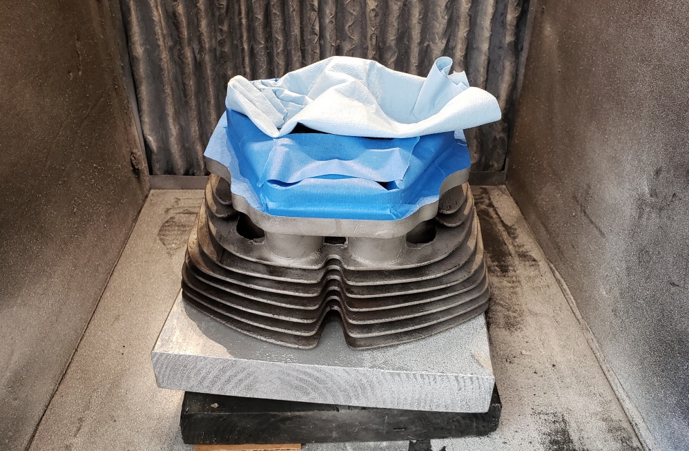
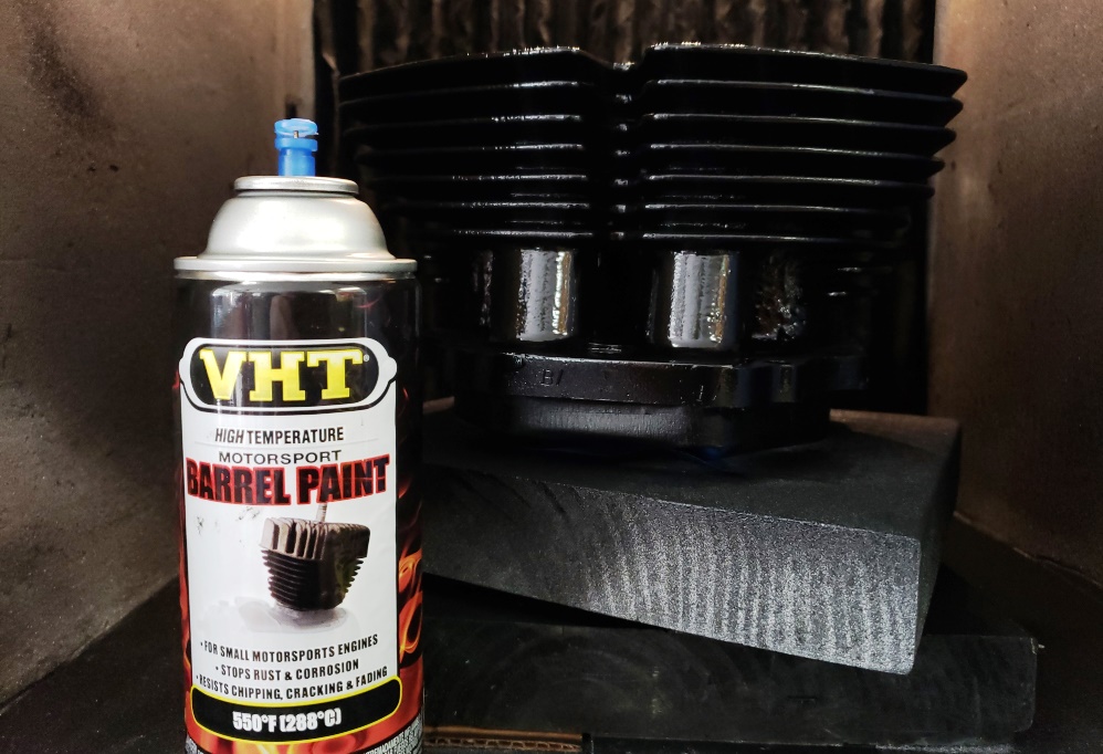
May 23, 2020 Painted the cylinders today. I use my powder coating cabinet lined
with cardboard so I can paint inside with
a fume extractor.
The first picture shows then upside down after a thorough cleaning and after masking.
The paper towel in the middle is
because once the bottoms of the fins are painted, I have to turn the cylinders over
without touching the paint � the towel
is just lying there.
The second picture shows them finished and shows the paint I use. It's a pretty
intense hour to paint them � all coats
must be done within one hour and if you go too fast you'll get runs. Also,
there are so many nooks and crannies in
a Norton
head it takes really careful spraying to not make a mess of it.
Once I was done with the cylinders, I moved on to the gearbox. It fought me but
I won. First was the little retainer screw
for the drive sprocket. I finally had the heat it and use a punch and hammer. Then
the sprocket nut would not budge and
I don't have a deep enough 1-1/2' socket so I started on the other side.
The outer case screws were Loctited in! Finally
got those out with an impact screwdriver. The cover, you guessed it, had the same
permanent crap on the gasket � finally
got the cover off.
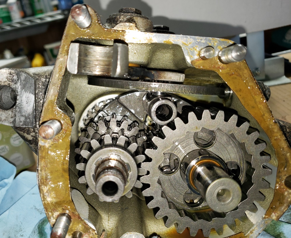
Was happy to see that it looked good inside. Getting the inner cover of was not
a problem but then the quadrant post was
Loctited in � ridiculous. Next issue � the gearbox still had the original, notorious
lay shaft ball bearing (2nd picture).
Generally, the lay shaft will slip out of the bearing, or the bearing will slip
out of the shell. Neither would happen.
So, I heated the case to 200 degree F. No joy, so I heated it to 300 degrees F.
No joy, so I heated it to 350 degrees
F and if finally came out � I've never had to go that hot before. Then, I had
to get the bearing off the lay shaft.
There's
no room for a puller so I had to clamp the bearing in my vice and drift the shaft
out of it � took a while but it went.
I think the sleeve bearing is good � it was too hot to check today. With a little
luck, the gearbox will be all done tomorrow.
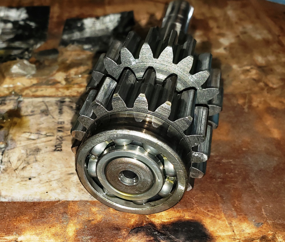
May 24, 2020 Got the gearbox all cleaned up, installed new seals in the outer cover,
and was ready to assemble when I realized
that I'm out of lay shaft roller bearings :-(
So, I stated on getting other parts ready. The triple tree is blasted and ready
for paint. The engine/gearbox cradle is
cleaned. It does not have the oil filter mount so I need to add that. More importantly,
the center stand holes are damaged
and I have to figure out what to do about that. In a perfect world, I would have
a lathe and I would make 850-style, but
over sized bushings for the center stand. Since this is not a perfect world, I'll
have to come up with something else.
I
may punt for now and use the one from my other Combat and worry about it later.
Ordered the pistons, bearing, and a bunch of parts from AN for this and other bikes
tonight.
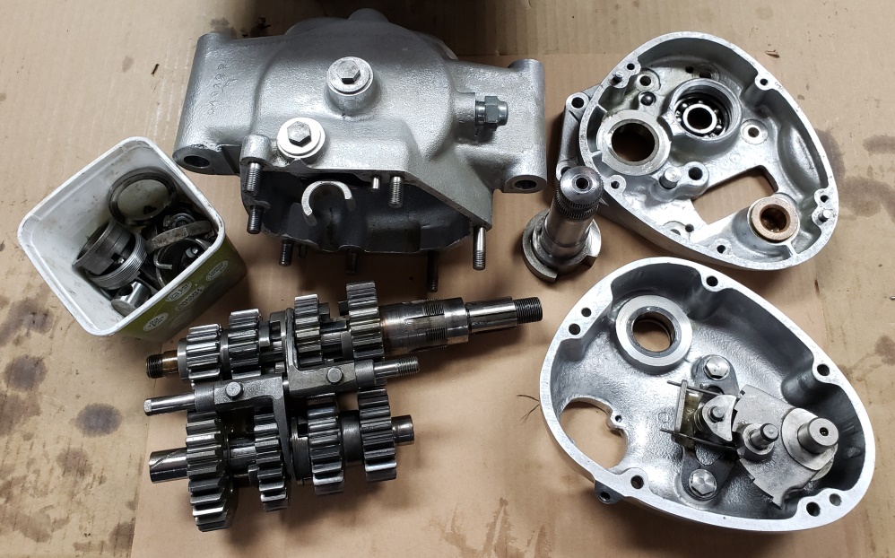
May 25, 2020 The center stand on this bike apparently was installed wrong for quite
a while. The holes in the engine/gearbox
cradle (cradle) were elongated and wallowed out and when I got the bike there was
no bushing in the center stand which also
was wallowed out. There are two versions of center stand and mounting hardware
to go with it. The 750 version (this bike)
would not work do to the holes being wallowed out. The 850 version would not work
due to the holes in the cradle and center
stand being too small.
To fix this, the cradle and center stand both needed to be modified for the 850
hardware.
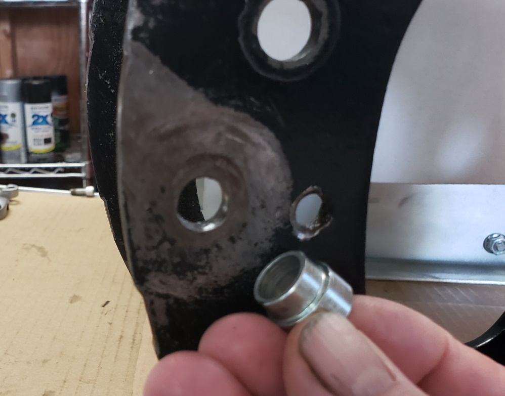
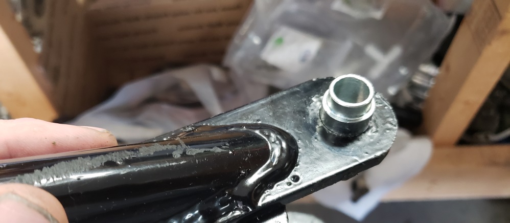
The first picture shows the hole in the cradle and the 850 type bushing. The smaller
diameter of the bushing needed to
fit in the cradle snugly. I used a drill press and progressively larger drills
to both round and enlarge the holes. The
largest drill bit I have is �' which is not big enough so then I spent forever
with a round file fitting the hole to the
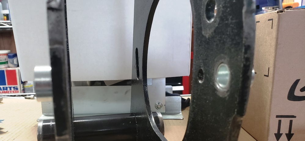
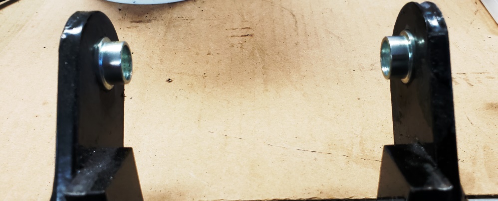
bushing. The 2nd picture shows the bushings properly fitted to the cradle. Notice
that the bushing does not reach all
the way through the cradle. When the thru bolts are tightened, the bushings must
not move.
The third picture shows the problem with the center stand and the forth shows the
bushings fitted to the center stand.
This also took forever :-(
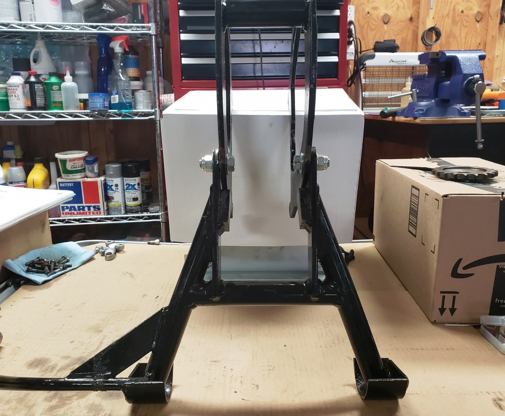
The fifth picture shows the center stand installed on the cradle as a test. It
works very well. The bolts are 7/16' which
is correct but they are just for test � I have the correct 7/16' bolts to install
once the bike is back on it's wheels.
The cradle has had all rust sanded and the swingarm sealing surfaces faced.
I'll paint it tomorrow. I won't
drill for the oil filter until I have the swingarm back. Even though I have
all he measurement, the swingarm comes
close to hitting the filter on the factory drilled cradles so I wants to double-check
the location before drilling.
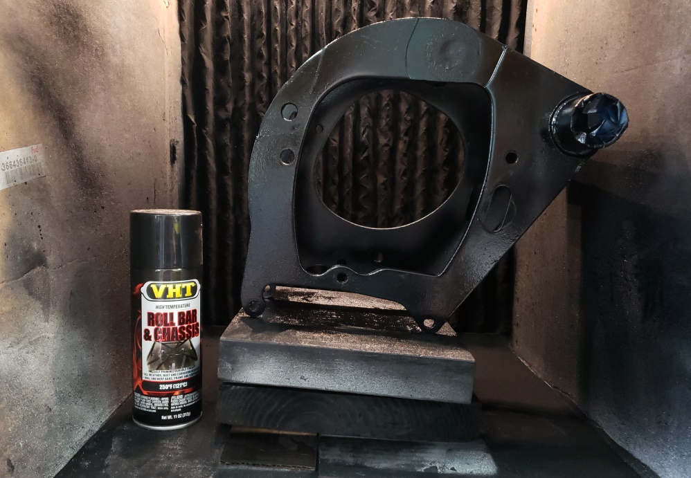
May 26, 2020 Painted the cradle today. The picture is after the 4th coat. Did
six coats.
Also blasted all (I hope) of the small black parts to get them ready for powder
coating. The battery tray was the most
difficult. It had the standard stick on rubber pads, but apparently as some point
battery acid got between them so it's
pretty pitted. Also, almost every arm was bent. Straightened all of them while
checking against a spare frame. The battery
box will look good, but not great, once coated.
Tracking says that the pistons and rings will be here Thursday. Assuming no shipping
hiccups, I can get back on the engine
then.
May 28, 2020 The pistons and rings arrived late today.
I got the cylinders ready:
- Lightly honed to refresh the cross hatching
- Made sure all the threaded holds were clear and that the head bolts threaded into
them nicely
- Cleaned very thoroughly and then sprayed all bare metal with WD40
- Reinstalled the tappets
- Verified the ring gaps - all were .012" - perfect
- Installed wires so I can hold them with the engine hoist while installing -you'll
see why tomorrow
I got the pistons ready:
- Rinsed them to be sure they were clean
- Installed the rings
- Installed the inner circlips - you'll see why tomorrow.
Then I cleaned the cylinder base studs and reinstalled them in the crankcase. Some
were so rusty that they wouldn't
come clean but I had some from other bikes so I came up with a decent set.
Not sure what I'll do about the nuts.
I normally replace the studs and nuts so I have some - hopefully enough to make
a decent set.
So, the cylinders are ready to go on. Wish I were 30 years younger - you won't
believe what I have to do these
days - you'll see tomorrow.
May 29, 2020 The normal way to install cylinders is to install the pistons with
rings to the connecting rods and then hold
the cylinders in one hand and manipulate the rings into the cylinders with the other
hand. I can still easily do that with
Triumph cylinders, but Norton cylinders weigh too much.
To resolve this, I do two things. First, I use my engine hoist to raise and lower
the cylinders as needed. Second, I partially
install the pistons from the bottom, lower the cylinders over the connecting rods,
push the wrist pins through, installed
the outer clips and lower the cylinders.
The first picture shows the cylinder rigged and checked that they are level which
make the whole process easier. The second
picture shows the pistons in the cylinders. The third picture shows the cylinders
ready to lower enough to push the wrist
pins in. I forgot to take one picture. On a Norton, the cylinders must be lowered
most of the way and then the base nuts
put on
since there's not enough room once the cylinders are all the way on. Using
the engine hoist makes this very easy. The
fourth picture shows the cylinders installed. The rotor is just stuck on the
crank to make it easier to turn the engine.
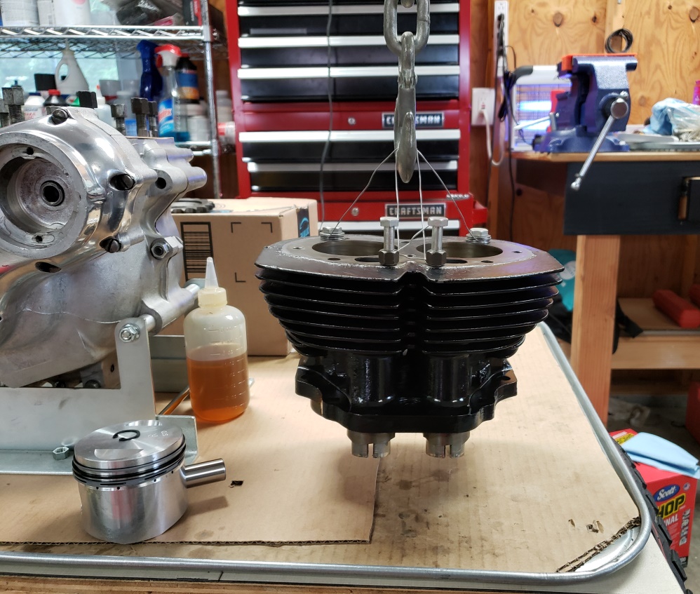
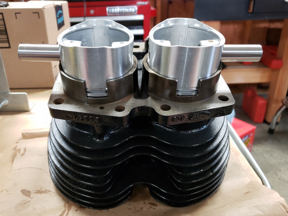
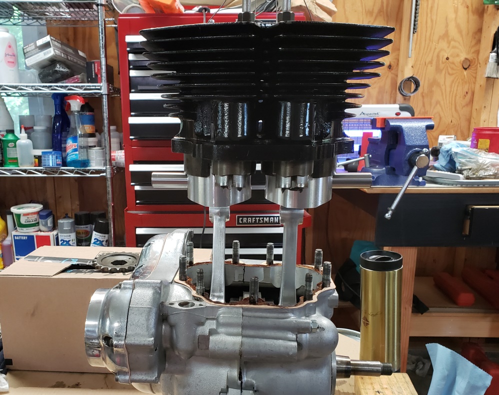
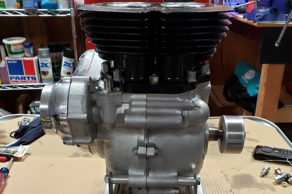
May 30, 2020 Didn't have much time today, but planned to get the head on.
Since several fasteners are difficult
to get to on a Norton head, I always check all threads to be sure they have no problem.
There's not much worse
that getting a Norton head on and then having a nut you can't start! While
doing that, I noticed the intake side
center stud was rough. On closer inspection, I realized that the threads were
about half there right in the tightening
zone. It's difficult to see in the picture but the discolored area is
actual quite bad threads. I figured
no problem - I have a bad head and the original head. I took a stud out of
the bad head with no trouble. However,
I worked on getting the bad stud out for two hours with no luck applying heat/cold/shock.
So finally, I went gorilla.
I clamped vice grips on as tight as I could make them and banged on the vice grips
with a big hammer - fully expecting
the threads to come out with the stud and needing a helicoil. Shocker - it
came out clean!
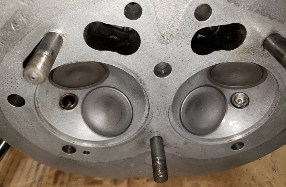
May 31, 2020 Got the head on and torqued today. The rockers are adjusted and the
rocker covers are restored and installed.
Actually this bike came with very poorly chromed rocker covers. The ones I installed
were from a parts bike. The intake
covers only took a little to polish up. Both exhaust covers had been over tighten
at some point and would have leaked.
I flattened than and then polished. One was smooth but with dings and scratched
� it polished OK. The other's surface
looked
cast aluminum. So, I sanded a little and then polished. It's no mirror finish
but is wat better that what came with
the bike
and
is in keeping with the owner's desired.
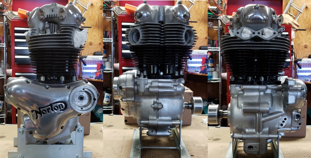
June 1, 2020 More or less stuck waiting for my Andover Norton order to arrive. Did
install the oil pipes and sump vent,
and cleanup the work area so I can do the gearbox as soon as the parts arrive.
June 2, 2020 Had a little help today so I was able to get some of the clutter off
the floor and up into the attic and while
doing that realized that I had a cradle and swing arm. Stripped that and used
the cradle to make a pattern to drill
the holes for the oil filter. Spent most of the day cleaning up - maybe I'll
trip less often now! Did turn
the painted cradle over so I could paint the areas that were not accessible due
to the way it was sitting. The cradle
is fully painted now.
June 5, 2020 Surprisingly, the parts arrived today - they were supposed to arrive
Monday. Installing the new layshaft
roller bearing went without issue. I reinstalled the sleeve gear bearing and
then the sleeve gear. I was sure
that the sleeve gear bearing was good but then I spun the sleeve gear - wow, the
rumble! So, out with it and in with
a new one.
The first picture shows preparing to tighten the sprocket nut (left-hand thread).
Have a look at the second picture without looking at the third so you can see the
mistake I make every time - see it?
No, OK, look a the third picture and read below it.
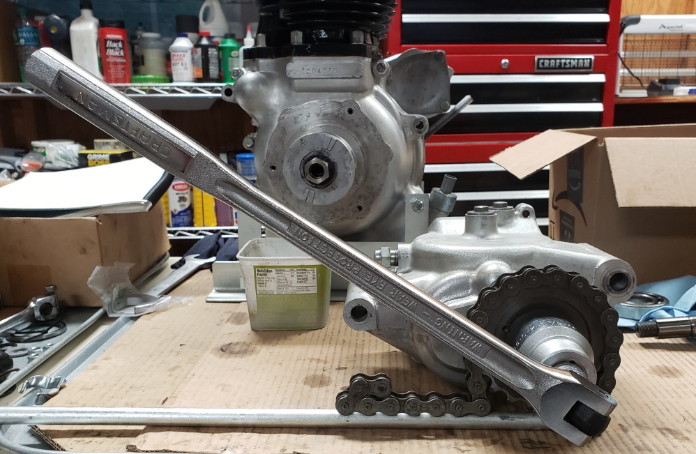
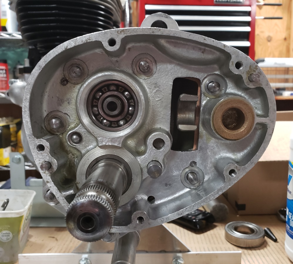
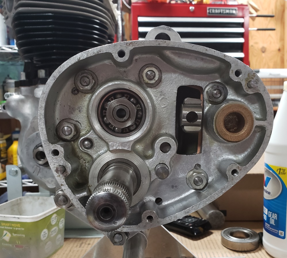
With the inner cover on, you cannot insert the pivot for the gearshift. There
are so many things that have to line
up to install the inner cover that it's a PITA to get on and off - you'd
think I would remember that so I didn't
have to do it multiple times! The other thing that can be a PITA is getting
the gearshift mechanism synced.
I did get that right on the first try.
June 6, 2020 Before installing the outer cover, the clutch actuator must be installed
and properly aligned. To do
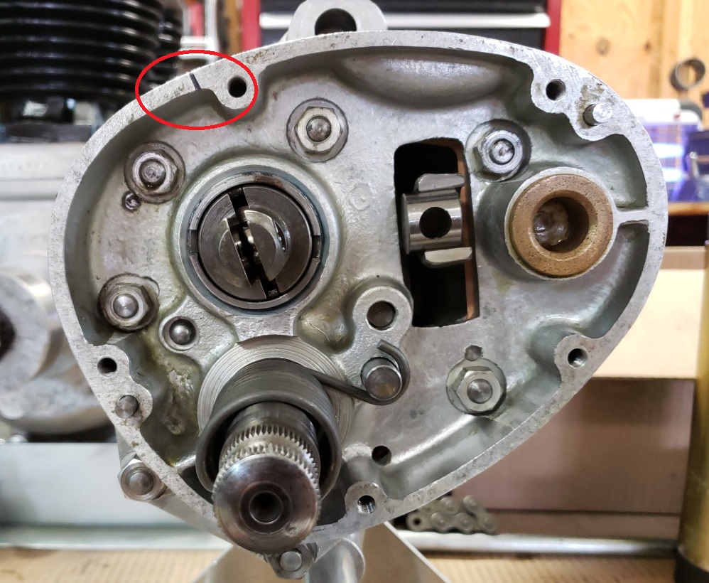
the alignment, I temporarily put the outer cover on and mark the inner cover in
line with where the clutch cable enters
the outer cover. Then I take the outer cover off and transfer the mark to
the edge of the inner cover (see inside
red circle. It's hard to tell in the picture, but the slot in the clutch
actuator is directly in line with that
mark. The second picture shows the gearbox ready for the outer cover.
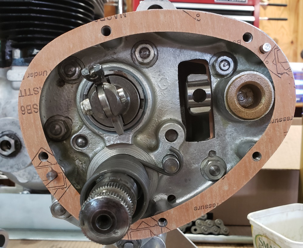
With the gearbox finished and tested, I
moved onto finishing the cradle and then installing the gearbox in the cradle.
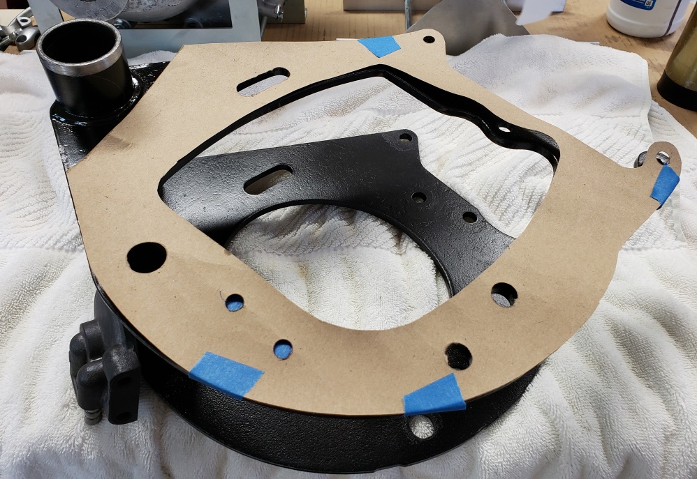
Below you'll see the template I
made to make for the oil filter holes. I put a piece of tape on the cradle
in the general area. Aligned the
template and trace the holes for the oil filter. Then removed the template,
center punched and drilled for 5/16"
bolts. I brushed painted the holes and moved on to installing the gearbox
in the cradle. When I took the bike
apart, the bolts were all wrong that held the gearbox. You had to fully disassemble
the primary to get the gearbox
out. It had the right bolts and nuts, just installed incorrectly and it was
missing the top spacer. That's
all corrected now. Tomorrow, I'll connect the cradle and engine and install
the rear isolastic. Depending
on how
long it will be before the frame returns, and what else is going on, I may finish
the primary before installing in the
frame.
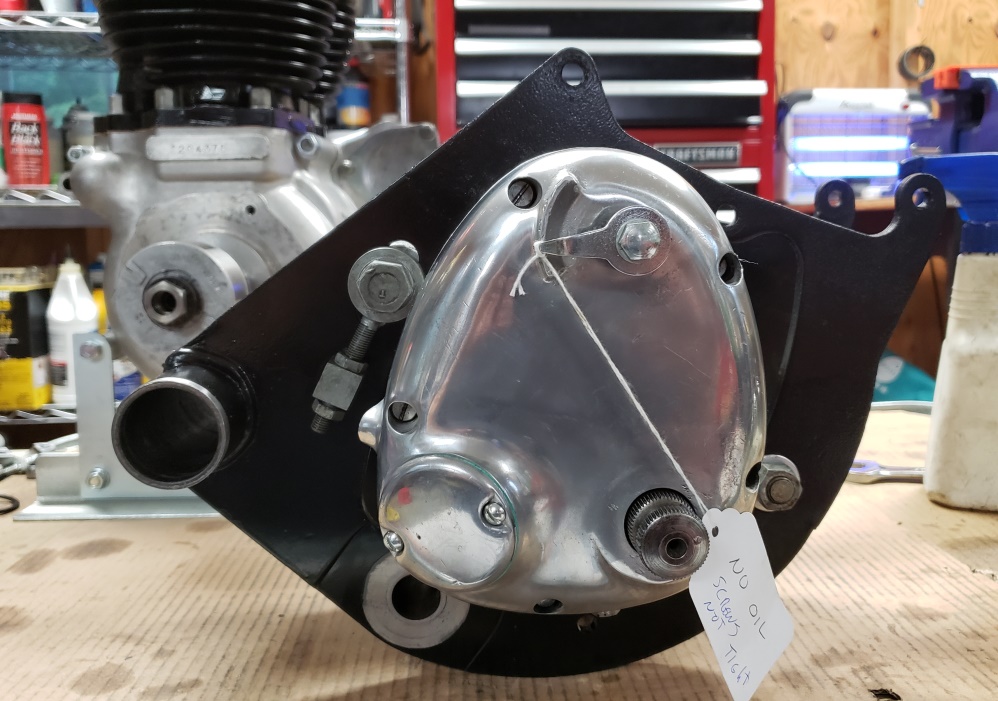
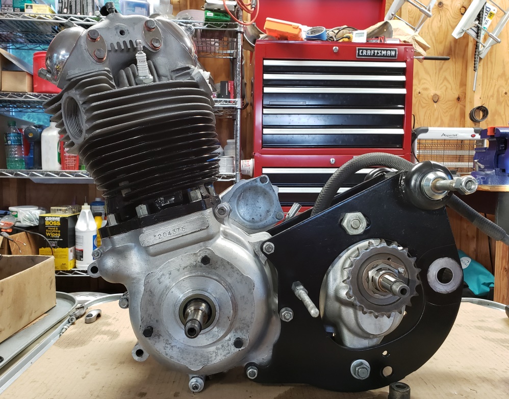
June 7, 2020 Ready for the frame. As you can see in the picture, the engine
and cradle are united and the rear
vernier isolastic is installed. I also temporarily installed the inner primary
cover so I could centralize the
support stud. That's much more difficult once the power unit is in the
frame.
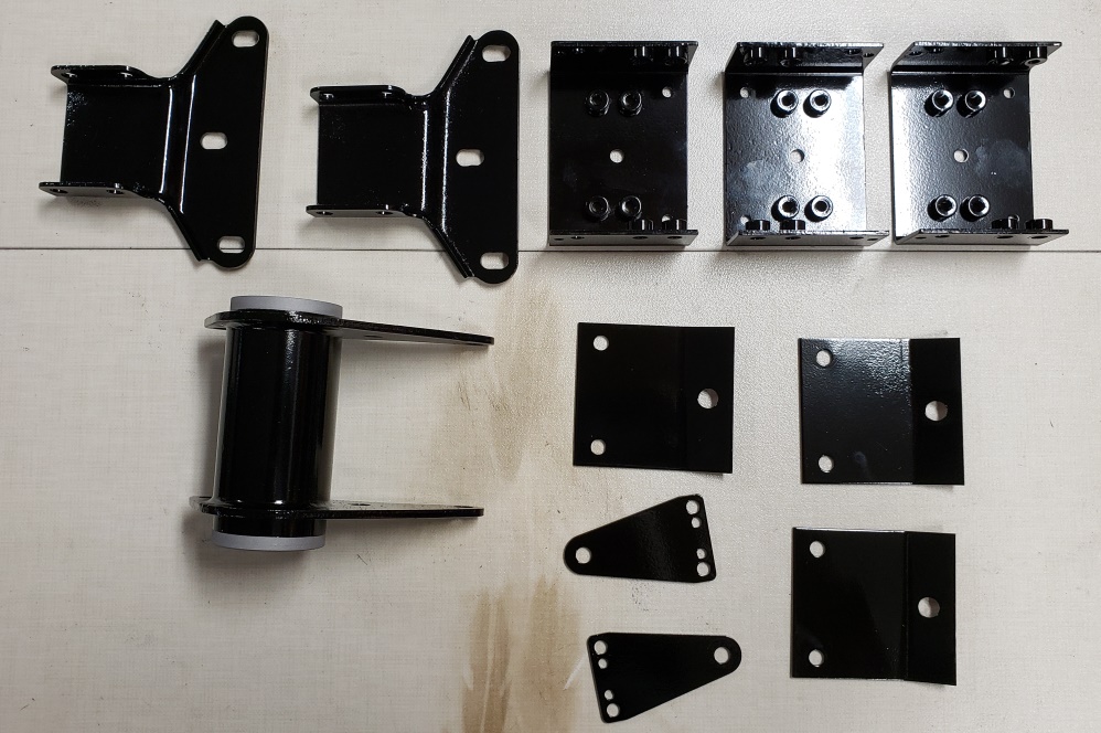
June 9, 2020 Powder coated today. Some of the parts are for this bike, some are
for another combat I'm rebuilding,
and some are extras.
The battery tray for this bike is done too, but it was too hot to get out of the
oven when I took this picture.
All these parts had a good bit of rust so none look perfect but at least they won't
rust again and they will look fine
for these bikes.
June 13, 2020 When building engines I like to set the rocker clearances and spend
a little time turning the engine over
to fill
the
oil ways while it's still on the bench. If I install the rotor, I can do that
but it still takes a good bit of effort
for arthritic hands. So,
I had a friend with a 3D printer make me a tool for the job. Watch the 7 second
movie below to see the tool in action.
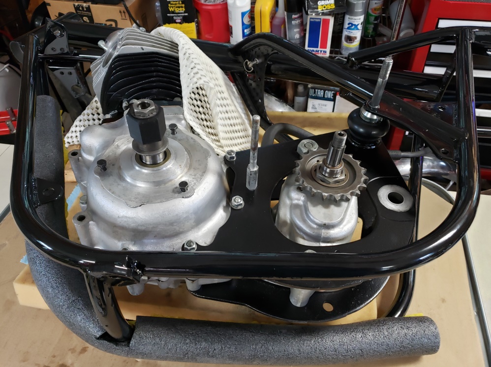
June 28, 2020 The frame arrived today � it looks great! While waiting, I
fixed a customer's
1979 Triumph T140, worked a little on a 1970 T120R I'm rebuilding, and started
working on a 1967 Norton 650SS for a
customer..
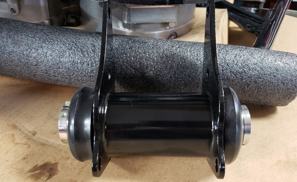
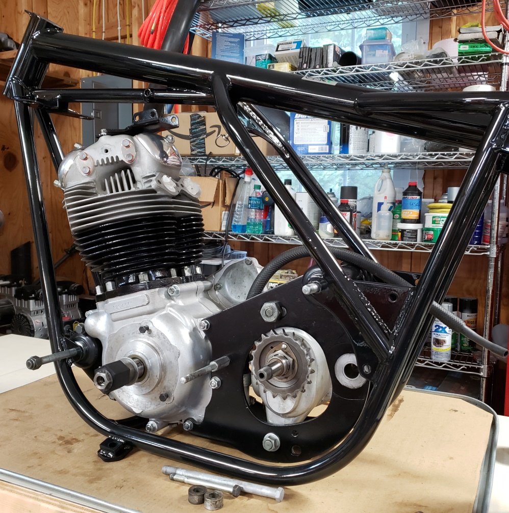
The first picture shows the power unit lying on its timing side on 2' thick
square of foam rubber and the frame in place
with the bolt in the rear isolastic. Notice the pipe insulation on then frame and
the foam over the head. That's a good
idea while lowering the frame over the power unit � it's a little fiddly and
it's east to bump the frame. Once
it's
about in place, it's simple to put the long stud through the frame and rear
isolastic.
The second picture shows the front mount with the Vernier isolastic installed. Now
for the fun � installing the front
isolastic.
The third picture shows the front mount installed with temporary studs. The
proper bolts plus a couple of spacers
are shown at the bottom. They were a mess. They have now been blasted
and will be re-plated and then
installed.
Now we can make progress with this bike!
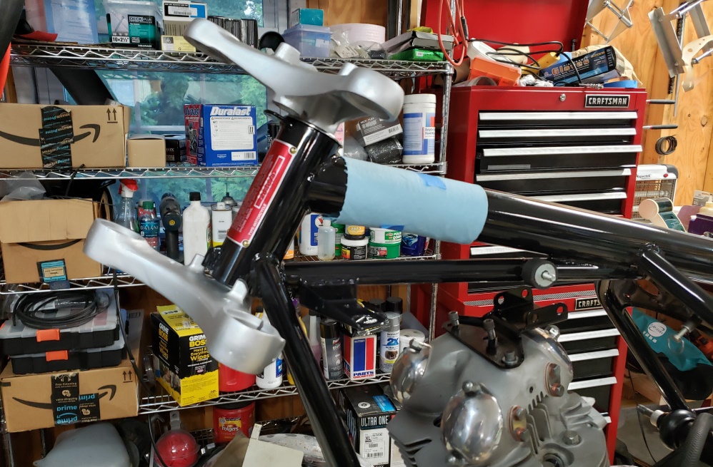
June 29, 2020 The front motor mount bolts are re-plated and installed. The
new certification plate is installed as
are the
steering bearings and triple tree.
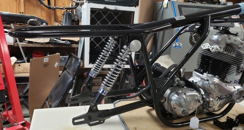
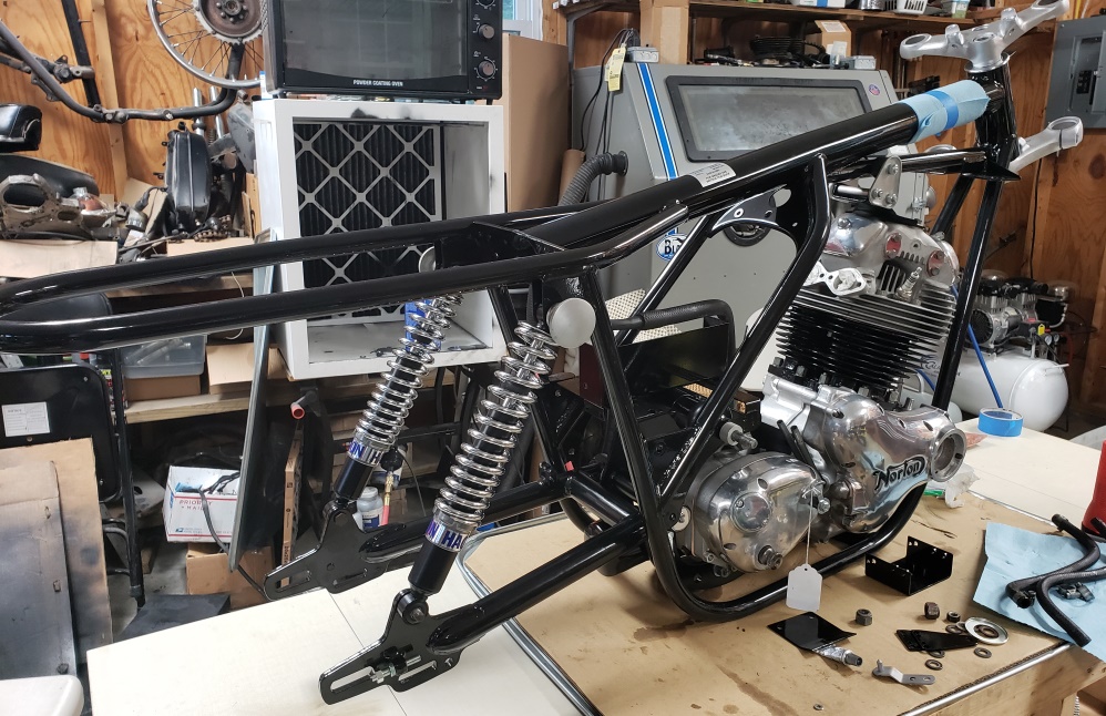
June 30, 2020 The swing arm and shocks are mostly installed. This took a while
as the powder coater coated the
inner edge where the bushing are installed so that had to be cleaned up. The
washers that were on the lower mounts
were wrong and I'm waiting for my AN order to have proper washers.
I still have to install the end caps, but the through rod is bad so I have to do
something about that.
July 1, 2020 The in earnest building has begun. The head steady hardware was all
rusty - it has been blasted and re-plated.
The swing arm through rod end was bad - that's been
brazed and is installed and the swing arm is filled with 140 oil.
July 2, 2020 Friday, I got my left little toe stepped on by a guy in boot while
I was wearing flip flops. That toe has
been broken three times in the last two years. Saturday, I was being stupid and
holding a Triumph seat hinge while
drilling a hole in it. The bit caught and the pain was bad enough that I didn't
look for a short while � I thought I
ripped my thumb off! Sunday night I ran my four small toes on my right foot into
the leg of my couch. Apparently, that
didn't hurt enough because I did it again in 20 minutes.
By Tuesday, my left toe hurt but I could stand that. My thumb and hand were twice
their normal size. My right toes were
black and blue and the one next to my little one was obviously broken and out of
line. My grandson was with me so I had
him set it. Wednesday morning both feet and my hand hurt but it was tolerable.
Today, my toes were so bad I could barely walk so I went to see the podiatrist.
He confirmed the broken toe and said
that is perfectly set and taped it.
So, I didn't accomplish much today. I did get the oil filter and lines installed
and the hardware for the Z-Plates
cleaned up. I tried to get the foot pegs off the Z-Plates so I can polish them,
but they must have been installed with
thread locker.
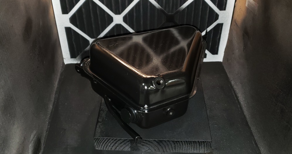
July 3, 2020 My foot is worse but I did get a little done. I was going to put the
oil tank in but it had more rust than
I could stand. Normally, I blast and powder coat them but in keeping with this being
a squared away rider, I cleaned the
grease and grime and then sanded off the rust and started painting. The pictures
didn't come out. The back and sides
are
done and tomorrow I can turn it over and do the front.
July 4, 2020 My foot is MUCH worse today. I can barely get around using crutches
so I got nothing done.
July 5, 2020 My foot is a little better today. I was able to (barely) get around
without crutches. So I took a lot of
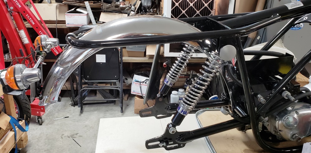
aspirin (not supposed to take any) and did a little work. The oil tank is finished
being painted. The horn is cleaned
up, tested, and installed. The rear fender is installed after quite a fight. I was
convinced that the frame rear loop
was bent, but I checked against others and it wasn't. It appears that the fender
was pulled into a larger radius than
normal � maybe the old frame was bent. With a lot of work, I decreased the radius
and now it fits � that would have been
a nice job for someone younger!
July 6, 2020 My ankle and foot are huge! Very little sleep last night. Went to the
doctor today and he prescribed
superman pills (steroids). Right now, I'm invincible and all pain throughout
my body is gone but I'm an accident
waiting
to happen. Didn't dare work on bikes today. Won't be sleeping much in the
next few days. If my leg swelling goes
down,
I'll go back to work and try to be careful (hard on steroids).
July 7, 2020 What toe, what foot, what wrist, pain doesn't exist for superman!
Put real shoes on so I wouldn't hurt
my
foot more and decided to get the rear wheel on.
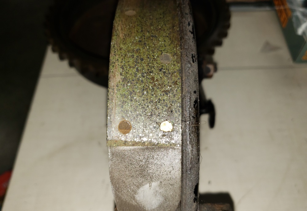
So, first I cleaned up the brake drum/sprocket � it had a good amount of caked on
grime. Then I had a look at the brake
� see the first picture � you do not want to see shiny rivets holding the brake
lining on! Rechecked the drum � a nice
sanding with 220 cleaned it up. Took apart the brake, with a great deal of difficult
� one shoe was seized on the pivot
post. Then I started cleaning � may have never been done since it left the factory!
The road grime was very difficult to
get off � at least I now know that the scraping sound was when I turned the rear
wheel before � it was that thick on the
backing plate. The second picture shows it all clean and the new shoes installed.
Interestingly, the actuator had no
grease at all and the hole was wide open � they are usually a bear to get opened
up. The pivots now have anti-seize and
the actuator is properly greased.
Then it was time for the cush drive fight. Installing new rubbers is usually a battle
even though I have a good system
for doing it. Maybe it went together easily since I had no pain in either thumb
and I'm superman. At any rate, it only
took five minutes to mount the brake side and then the wheel itself. See picture
three � progress!
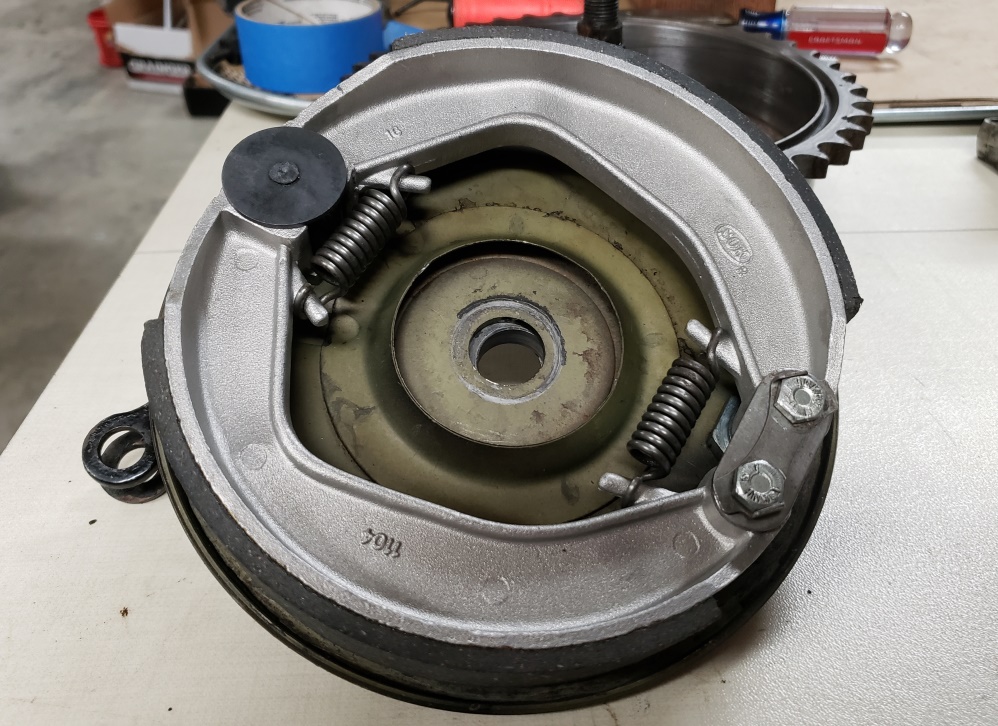
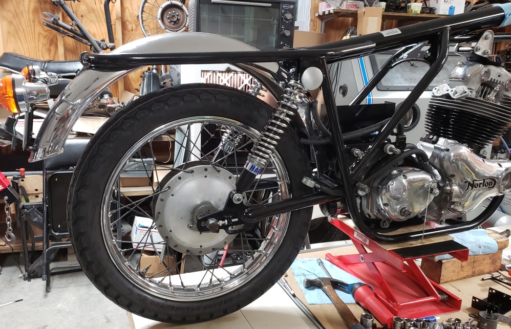
July 8, 2020 My leg is a little better and I'm stil on superman pills so I tackled
a job that always seems simple but
is often a PITA.
Over the years, Norton made minor changes to the mounting holes on the frame and
on the coil bracket. This coil bracket
probably came with the 850 frame I removed. On most 850 frames, the holes are elongated.
This 750 frame had just the
right size holes and the threaded holes in the coil bracket need to line up with
them. Also, we had the frame power
coated. After I removed the powder coat from the holes, they were still too close
together by about a 1/16 of an inch.
It's an awkward place to work but with a round file I was able to elongate the
holes enough to make it work. I coated
the bare metal edges and installed. Then I cleaned up the reflectors, coils, and
coil brackets and installed them. This
always seems like it should be a 10 minute job, but it turns into a couple of hours!
I don't remember if I mentioned it before, but you can see the re-plated head-steady
plate in this picture too.
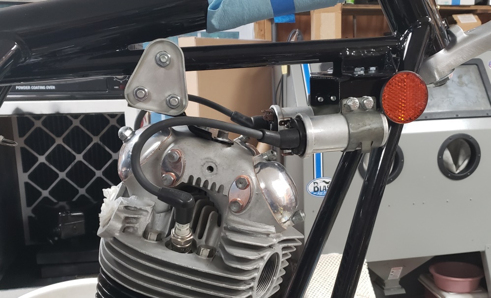
July 15, 2020 My latest AN order came in today so I'm back on this.
It's a disease! I was going to installed the oil tank, but noticed that the
part that shows with the cover off had a
lot
of dust in the paint - I have no idea how that happened. So, I wet sanded and repainted.
Yes, I know it does not show
and the tank was rusty and pitted but I couldn�t leave it. It still won't be
beautiful but it's not embarrassing
now.
Took the forks apart. They had very old ATF in them but surprisingly no water. Also,
no significant rust and the
dampers, springs, and sliders seem to be in good shape. I'll check the sliders
better after I get them cleaned up �
as
usual there is a lot of sludge in the bottom. The tubes on the other hand have to
be changed.
July 16, 2020
Installed the oil tank today. That went fine.
Then I cleaned and inspected the fork sliders. Besides the usual sludge and the
drain plugs being put in by a gorilla,
they are excellent inside. I can't detect any wear. I normally change the bushings
but might not this time. The bottom
bushings feel fine in a quick test in the sliders and the top bushings feel fine
on the fork tubes even though the fork
tubes tore up the seals. I'll installed the top and bottom on the new tubes
and check again. If still good, it will
save
some money to not change them. The rest of the internals are in great shape.
The sliders had a lot of scratches, dings, and dents. In keeping with the owners
desires, I won't go crazy making them
perfect, but I did spend time with 600 wet and dry paper removing the worse and
then with 1000 wet and dry. Tomorrow,
I'll spend time on the buffer. They will look really good, just not perfect.
BTW, I normally don't take the forks off the bike without preparing to take
them apart. This time I was in a hurry and
made it harder on myself in the end. My normal procedure is:
- Remove the fork cap nuts
- Drain the oil
- Loosen the collars
(06.1137) using a strap wrench, NOT channel locks!
- Remove the caliper
- Remove the wheel
- Remove the fender
- Remove the bottom bolts
- Pull the springs and damper out the top
- Pull the sliders off (yank them a few times and the seals and top bushings come
out)
- If the tubes or fork ears are going to be replaced:
- Loosen
the bottom triple tree pinch bolts
- Remove the tubes
This makes several steps easier since the bike is holding
most of the parts while you work.
July 17, 2020 Expected to get the forks done today, but spent too much
time on the phone being answer man.
They are all buffed and together except the collars. They were rusty and well chewed
up by channel lock wielding
gorillas in the past. I planned to replace them but didn't realize I was out
of them. So, I filed the channel lock marks
as best I could, sanded, and sand blasted. I'll re-plate then and install tomorrow.
I did end up using the old bushings
� there was no need to change them. Of course, the bottom fiber washers, paper washers,
and seals have been changed
and new short gaiters will be installed once the collars are on.
July 18, 2020 The collars are re-plated. Maybe not as good as new, but
quite good nonetheless.
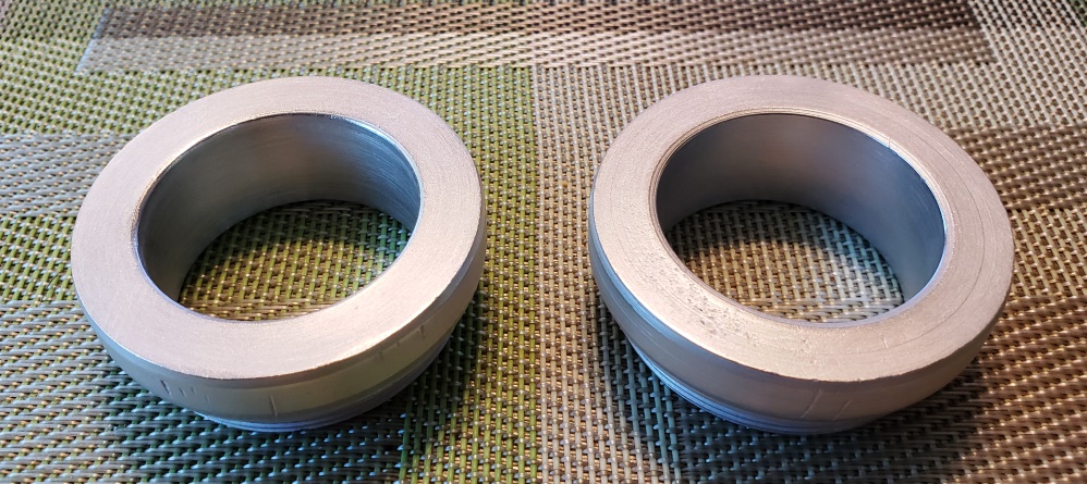
The forks are done and on the bike. On a Norton, the fork ears are secured by two
O-rings at the bottom and one at the
top. So to put it together is a little complicated, here's how I do it:
- The lower part of the triple tree is left loose
and dropped down about �"
- The two bottom O-rings are put in the bottom slot and held with a little grease.
- The top
O-ring is put in the slot in the top and again held with grease.
- Each tube is slid up through the bottom to a little
under where the would meet underside of the top of the triple tree
- The pinch bolts are snugged just enough to keep the
tubes from falling.
- The fork ears are slipped over the forks and slid down to the O-rings making sure
the O-rings stay in
place.
- The top of the triple tree is rotated to line up with the fork tubes
- Then using three of your two hands, you
loosen one pinch bolt, hold the fork ear in place, slide the tube up into the top of
the triple tree, install the top nut through
the instrument
case, and finger snug it.
- Then do the other side the same.
- This is critical: you temporarily install the
headlight shell. If you don't and you do the next step you won't be able
to align the fork ears!
- Tighten the bottom nut snuggly � not real tight yet - the fork ears will now be
locked in place.
- The fender and front wheel need to be installed before tightening everything.
The front axle has been de-gorilla'd and re-plated. No more beating it in and
out of the fork tubes! I couldn't
stand the front fender bridge so that's been painted - expected to have the
front fender and wheel on today, but that's
the way it goes - I can't help myself. The headlight shell it terrible
but at least it is easy to change later.
The instrument cases need cleaning up too, but you can't put the forks together
without them, so they will come back
off at some point.
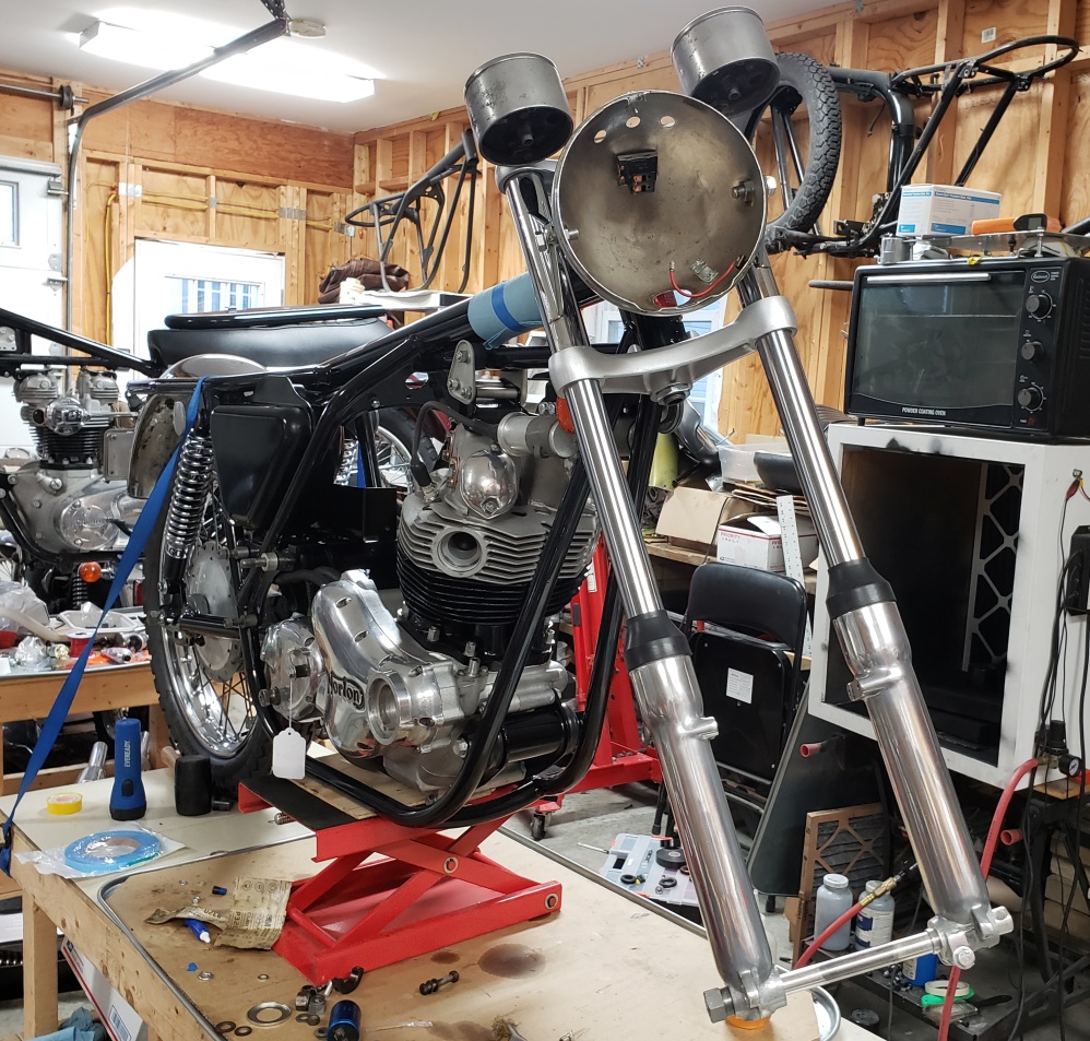
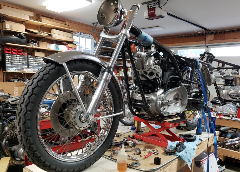
July 19, 2020 It's a roller! The front end is together and aligned.
The left side bearing
cover/spacer was damaged and rubbing on the wheel - took a while to see why - it
is for a drum brake! Fortunately
I had a new one or I would be stuck on the front wheel. The instruments are
back off to
polish the cases. The front fender has some scuffs but it looks good.
The inner primary cover is cleaned, polished, and installed. A bullet was
dodged there! The master link has
been clipping the seal plates but never caught and ripped them apart. Most
likely the center support was not
properly shimmed - it is now, but I'll put the master link in backward nonetheless.
The chain is on, but it
has some frozen links so it needs to be changed - I put it on because it's easy
at the point and it will make it easy
to
pull an new chain on.
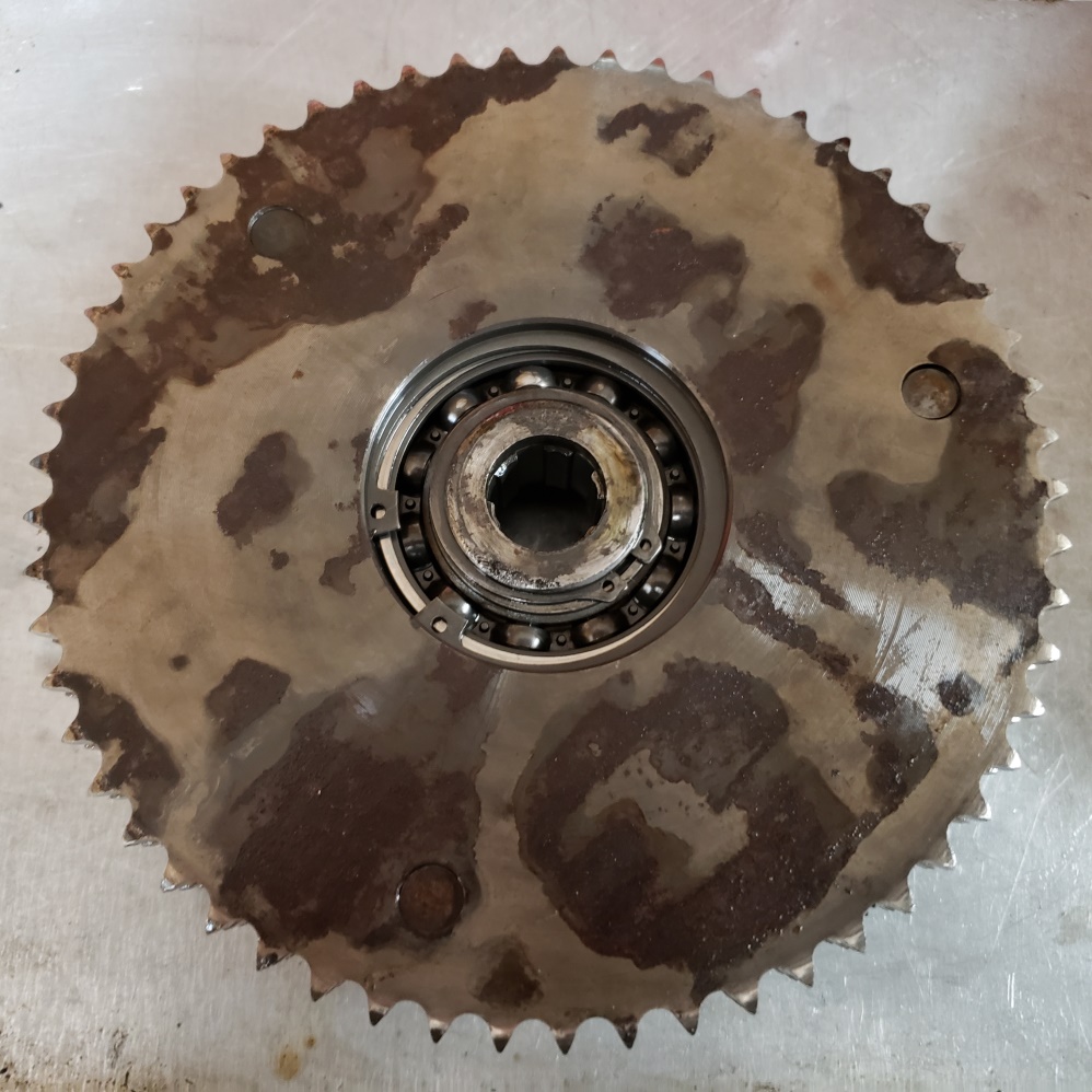
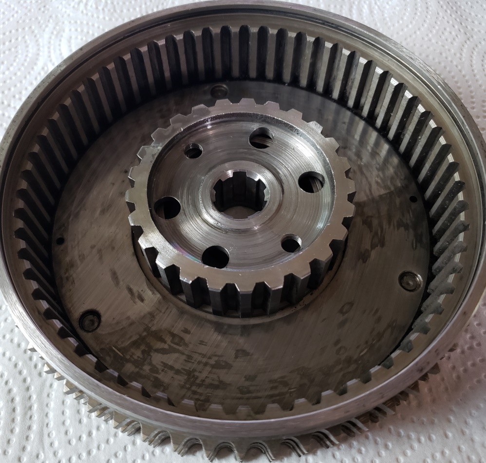
I expected to have the primary back together today, but when I turned the clutch
basket over to inspect the bearing I
realized that there's more to do. There is crusty rust on the back of
the clutch basket that must be removed.
Once removed, the basket will be fine to use. The bearing feels gritty.
I'm not sure if it is dirty or bad
at this point. The clutch basket is are now apart and the bearing is out so
I can clean it all and properly
inspect the bearing. The splines look perfect - not sure why the rust is on
the back.
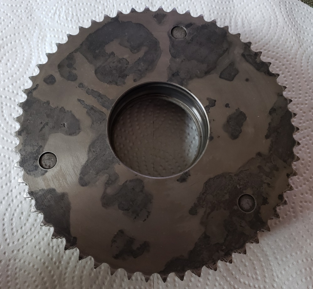
July 20, 2020 It's hard to tell in the picture, but the rust is gone and in
most places you cannot feel anything � the
metal is just
discolored. Not sure where the cakes of rust came from. I used a razor blade to
scrape off most of it, wet sanded, and
finally soaked in rust remover. The second picture shows the splines which are in
excellent shape. They did have a great
deal of caked on crud which WD40 and a lot of brushing removed.
However, I'm stuck now. The bearing is bad and I cannot find the one I'm
supposed to have in stock. I ordered one
from
Amazon today which is supposed to arrive Thursday. Hopefully then I can finish the
primary.
The instrument cases are polished and installed and I found a headlight shell in
my used parts that is MUCH better than
the one on this bike so I'll donate that to the cause.
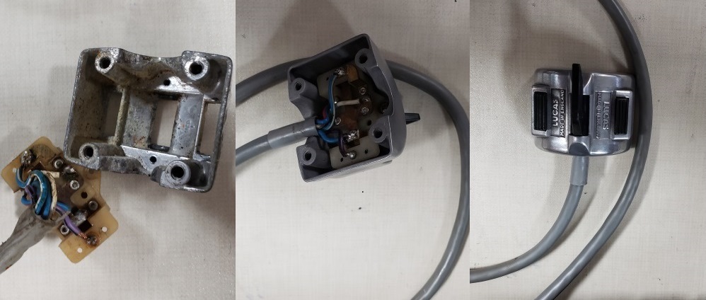
July 21, 2020 Since I'm stuck
waiting for the clutch bearing, I decided to get the handlebars on, and the front
brake bled. What's the
saying? "The best laid plans of mice and men". Mounted the handlebars
and got the master cylinder and switch consoles
out. The master cylinder looked bad (paint missing) but I was going to let that
go but then I looked at the switch
console! The first one's wires were a mess, most of the contacts didn't
work, and just look at the housing. I had
a
better cable that I had already cleaned and tested so I blasted the housing and
buffed it. The pictures aren't great
but
trust me � it looks good.
Then I figured I better check the other one while I had everything out to rebuild
them. That one was even worse � notice
the red oval � the whole side is missing and two wires were disconnected. So, I
cleaned up and repaired another one I
had.
BTW, getting the housings and internals is hard and costly. Getting good, correct
color, and correct wire color cables
is nearly impossible. Therefore, I've developed a procedure to restore the cable.
The two in the picture were basically
black before I restored them. They aren't perfect, but they look plenty good
for a rider.
Then, I couldn't help myself. Once a master cylinder is part, it only takes
seconds to blast one (the paint is
terrible). I painted it. I sometimes powder coat them, but the prep for powder coating
on a master cylinder is very time
consuming.
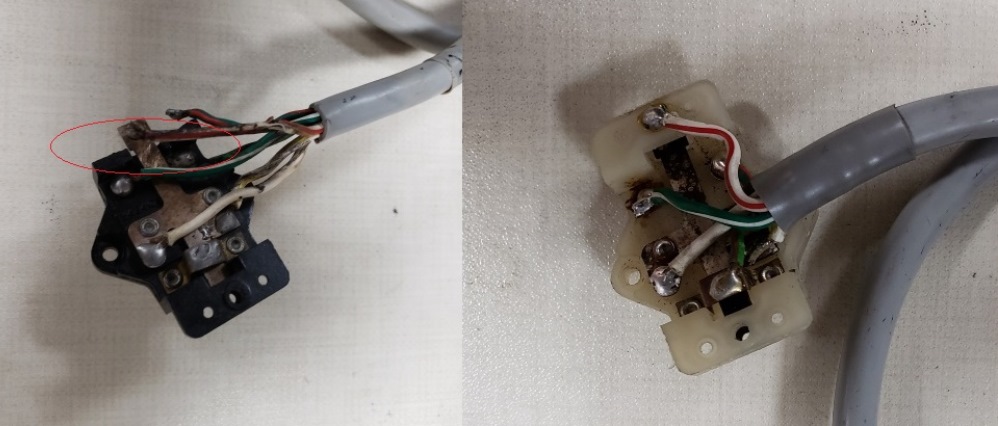
July 22, 2020 Finished the second console and decided to paint the clutch
lever mount. Also buffed the front
brake and clutch levers. The clutch bearing came in so started on the primary
again. This bike had a
lock washer and nut to hold the clutch on. That was correct for 72, but the
lock washer on the bike incorrect (way
too flimsy). I prefer the later style with a tab washer, plain washer, and
nut so I'll install that - it seems
much
safer to me.
July 23, 2020
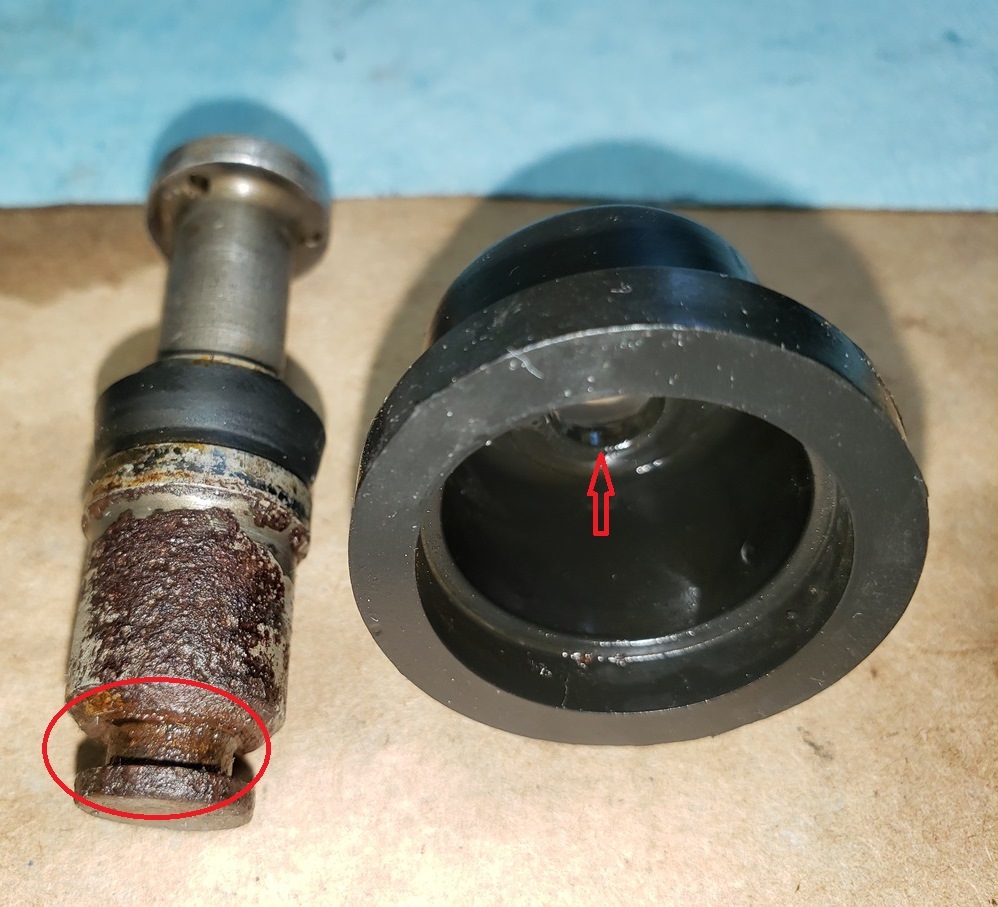
Two steps forward, one step back! Before reassembling the master cylinder I inspected
the components. The first picture
shows the badly rusted piston and the outer boot. The rust wallowed out the hole
in the boot and the brake fluid on the
inside of the boot implies that they was a minor leak. Since the rebuild kits are
inexpensive and the master
cylinder is easy to rebuild, I rebuilt it.
Then I installed it on the handlebar with the rebuilt switch console and
verified that the switch console worked and that nothing was shorted to the handlebar.
Then I tested the brake switch.
It had rust on the mating surface but I was able to clean that up- its installed
finger tight � will be removed to
tighten the hose (easier that way).
Then I installed the hose � another step back. See the second picture. The hose
is
way too long. I don't know if I have one or will have to order one. The fourth
picture shows the master cylinder
installed with the hose just hanging.
Then I installed the clutch lever housing and switch console. You can see that in
the third picture. Also in the third picture you'll see that the clutch and
crank components including the rotor are
installed. The stator is not installed because the wires are chaffed and very hard.
I did do some testing and the stator
seems electrically OK. I have to figure out what to do about the stator � I'll
go through the ones I have and see if
I
have a better one. I sold my last new one I had. I thought I took pictures of the
stator but I guess I didn't since
I
can't find them.
BTW, saw the podiatrist and got a steroid shot in my foot � superman mode returned
at about 3pm. Will be gone around 3pm
tomorrow � it's a shame that steroids are bad for you.
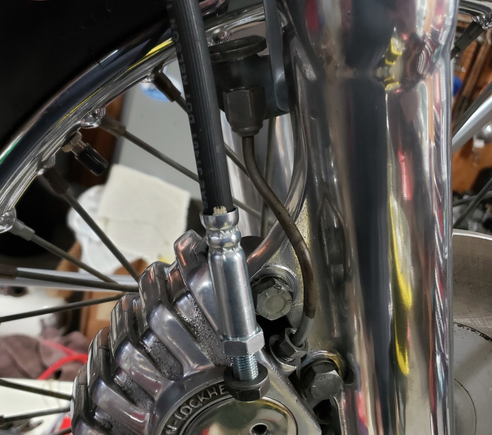
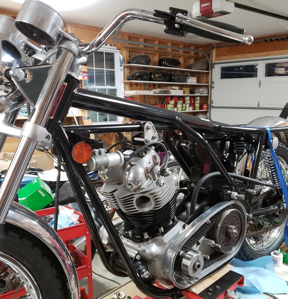
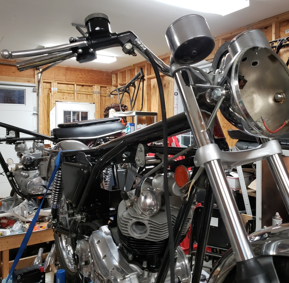
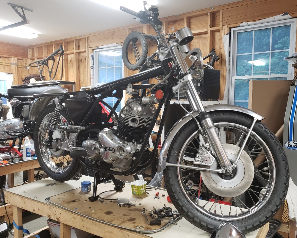
July 24, 2020 Had company today so I put them to work. My Grandson cut a new
chain from my bulk chain so that's
done but most importantly, the center stand is on! That's always a big
event since I can't get one on by myself
these days. The bike has quite a ways to go before I take it off the table,
but at least now it could come off the
table and stand on its own - it's standing on the center stand on the table
now. To me, that's one of the
biggest
milestones for a rebuild.
Also, ordered a braided stainless hose. They cost less than ordering new rubber
hoses from AN; and, they: improve
the braking action, are DOT approved, and are made in the good old USA.
July 25, 2020 I have a couple of small project I need to get done so I'll be
off this for a short while.
July 31, 2020 Made a little progress. The timing side Z-plate is cleaned and
polished and it and the footrest are
installed. The drive side is a mess. There is one missing stud and nut
and the other two nuts are stripped
so they cannot be unscrewed. I'll have to cut those nuts off to get the
footrest off. I cleaned and polished
a Z-plate I had and installed that on the drive side. I found a stator online
from a guy who didn't know what
they
are worth - that should be here in a couple of days and then I can finish the primary.
By then, I'll have the
footrest off the Z-plate. The primary chain and drive chains are adjusted.
The clutch cable had several bad
places but I cleaned it and used heat shrink where the covering was bad. At
some point in the near future, a new
clutch cable is in order. Anyway, it is installed, the gearbox is filled and
closed up.
So, it's getting close to wiring time.
August 1, 2020 More progress. Got the foot peg and rear brake off the old
Z-plate so once the primary is done that
can all go on.
The front brake hose is installed and the brake is bled. I counted this time
- from empty, it took 97 brake lever
squeezes to bleed the brake.
The muffler mounts were a mess. I cleaned them for a while and gave up.
I had a set of stainless ones that
were messy so I couldn't sell them - I polished them a little and put them on
loosely. There's always a lot
of slop in them so I like to do the final
tightening when I put the exhaust on. The passenger pegs and mounts were a
mess as well. The pegs themselves
have been painted and the hardware is blasted and will be repainted.
I"m doing a little R&D with this bike. It had the original plastic
rocker feed lines. The braided stainless
kit that AN sells are very expensive. I'm working with the guy who makes
the brake lines to make them. The
first try was 90% there. In a week or so, I should have a perfect set to install.
August 4, 2020 The stator arrived and it is shockingly good - it has a 1979 date
code. The primary cover is chrome
plated, and as usual that lets things down. It was plated with chrome only
so it is a mess. It's a shame
because it doesn't have the foot peg damage so many have. The foot peg
and rear brake are not perfect but they
cleanup up nicely. The rear brake cable is not usable; so, I need to install
a new one, the safety return spring
and rear brake switch to finish that area.
You'll notice that I've painted the timing mark white and the area around
it black. The rotor has a TDC and
BDC
mark - it's a pain when timing if you don;t know which is which. I also
verified the timing scale in the primary
cover - this one is perfect - that seldom happens!
The center nut was in terrible shape but I had a half-decent one so I Installed
that - no point in a new one with that
primary cover!
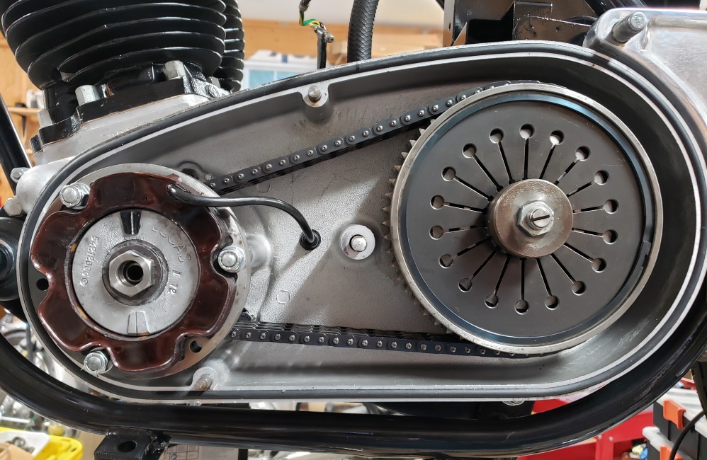
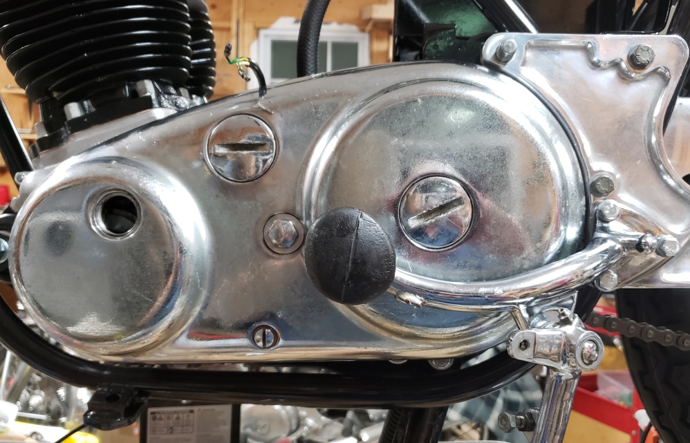
August 6, 2020
The owner has decided that the primary cover needs to be replace so I have a new
on on order - the available ones on
eBay are listed for nearly the same as new.
I forgot to mention the other day that I rummaged through my signal parts and between
them and
the ones that came on the bike, I have made a decent set. I have new ones
in stock, but the originals are better even
if they don't look as good. I may have mentioned that the headlight shell
that came with the bike was pretty ugly.
Well I had a used one which was quite a bit better, just not perfect so that and
the turn signals are installed.
I normally wire bikes, especially Nortons, from scratch. For more on that,
look here
and here.
This time, I not going to do that for several reasons:
- It's a lot of labor
- My component supplier has raised prices so much that it costs a lot in components
- The headlight harness is in good shape
- I thought that the main hardness was in good shape - more on that below
This bike will have a Tri-Spark ignition and Tri-Spark MOSFET rectifier/regulator
and an oil pressure switch instead of
the silly assimulator. So the Zener, bridge rectifier, assimulator, ballast
resistor, and condensers and their wiring
is
not needed. After cleaning the main harness I started unwrapping it so I could
get rid of the unneeded wires and
breakout other wires where they are needed.
I like working on bike but don;t like dirty hand - I clean them often. The
harness is about 2/3 unwrapped and my
had got that dirty in about 10 minutes of unwrapping. The entire hardness
should have take 20-30 minutes to unwrap
- took me an hour to get this far! Why? Although the harness was properly
made using hardness by the factor,
over the years, people have attacked it with plastic electrical tape. DO NOT
USE PLASTIC ELECTRICAL TAPE ON
HARNESSES!!!!
Vinyl hardness wrap has no adhesive, is flexible, is water and oil tight, easily
be cleaned, and is not expensive.
Fortunately, the wires are quite good, just dirty. I will spray with WD40 and wipe
each wire, then wipe each wire with
denatured alcohol. In keeping with my normal wiring, I'll reduce the connector
count under that tank as much as
possible, run a single
14ga ground rather
that the snaking 18ga ground wire that is standard, Run a 14 ga Blue/Brown to the
fuse and on to the master switch and
two ignition (white wires) circuits - one for actual ignition and one for lighting
other than the headlight.
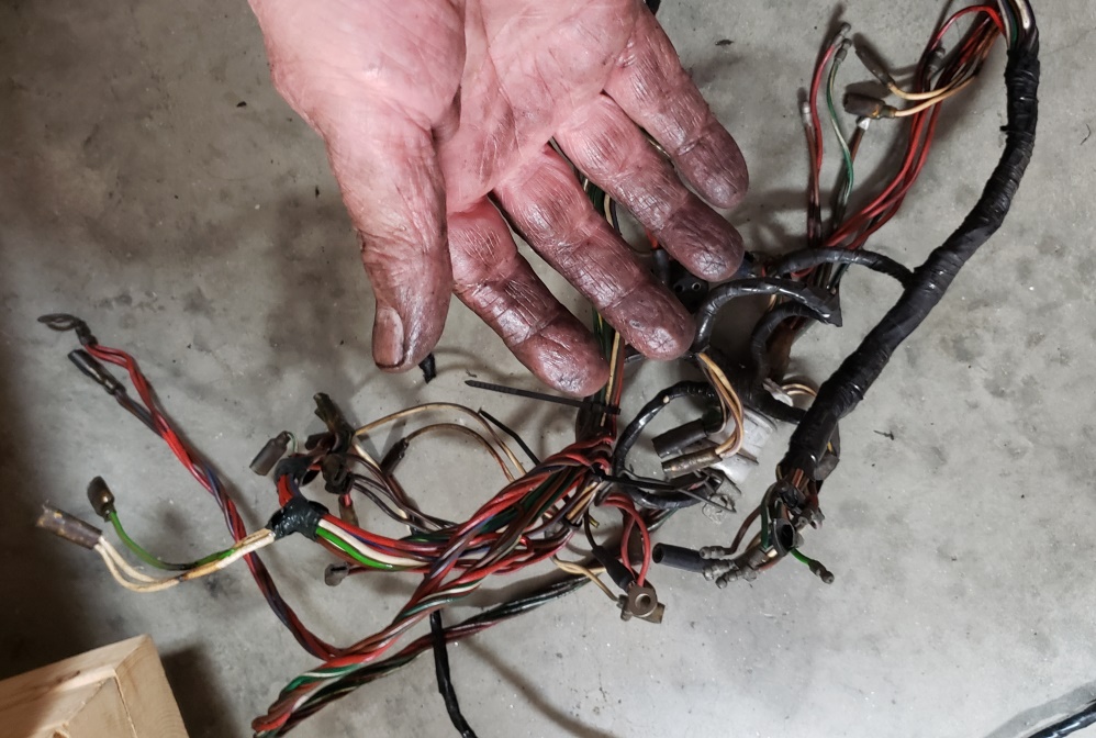
August 8, 2020 "The best laid plans of mice and men".
While cleaning the wires I discovered that all the wires to the tail light had been
chafed bare in three locations and
had over heated as well. Also, there were some "work hardened" wires especially
ground wires. So, what started
to be a
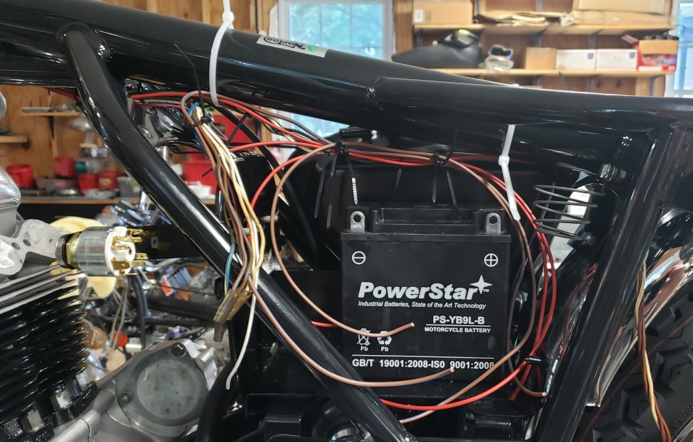
clean/remove excess/re-wrap turned into a big overhaul. The first two pictures show
the harness halfway made. The brown
and white wires on the right of the second picture also were damaged and have been
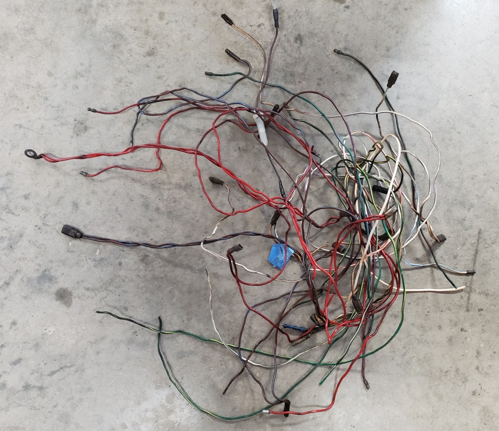
replaced. The third picture shows
most of the extraneous and bad wires I've removed. Since I'm re-making the
main harness, I'm doing it exactly
like I
normally do from scratch; except, that there will be more connections under the
tank than I like. There will be quite a
few less than stock though.
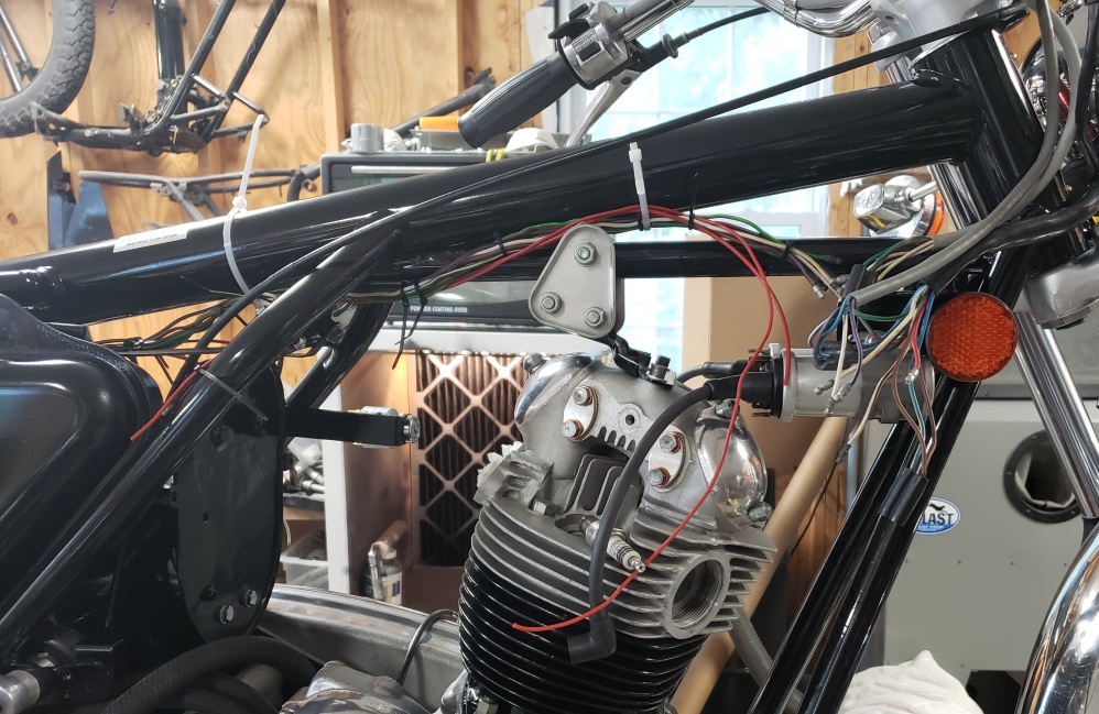
August 11, 2020 I've done a little more on the wiring, but mostly have been
stuck on other things for a couple of days.
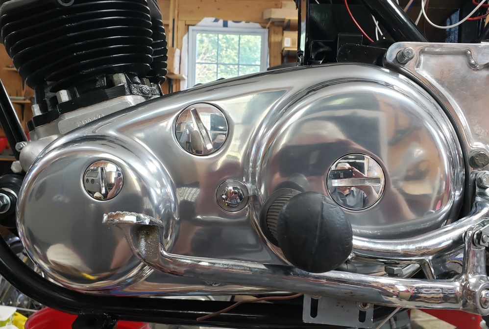
I did install the new primary cover today. I'm two for two � I put the engine
at 30 degrees BTDC before I took the old
cover off and when I put the new cover on it showed 30 degree so the timing scale
in both is accurate. I didn't
polish the cover - that's the way it came from Andover Norton. That you
can see my white hair in it tells you
that
it's pretty well polished - it could be made like a mirror, but it really good
just like it is.
Now, I suppose that crappy footrest rubber needs to be changed!
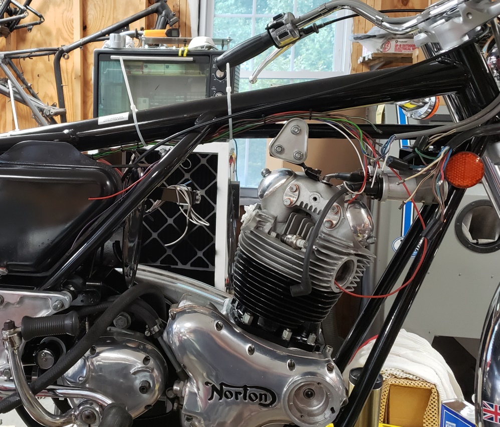
August 13, 2020 It's probably is not clear from the pictures, but a good bit
of progress was made today on the wiring.
All main harness wires are run and all breakout locations are defined. Next, circuit
by circuit:
- The wires will be
trimmed to length (if needed)
- The wires will be terminated (if not already)
- The circuit will be tested
Once the entire bike is wired and tested, I'll add even more zip ties to make
sure nothing moves. Then I'll remove
the harness from the
bike and wrap it.
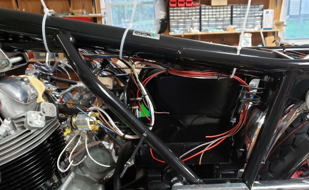
August 14, 2020 I didn't have a lot of time today, but I did make some
progress. When I start terminating and
testing, I get the taillight and rear turn signals connected first so I can check
them without fiddling around.
On a
Norton, the frame, and therefore rear fender are not reliable grounds. So, a ground
wire is run to the taillight by the
factory. In theory, that ground also grounds the turn signals. Probably before any
corrosion starts, that is true,
especially if paint is scraped off where the turn signals bolt on.
I never rely on that! That's especially true when
all
the taillight parts are rusty and I powder coat them which I did in this case. Also,
the turn signals were a mess. Like
with the front ones, I went through my parts and made two decent ones � now I'm
officially out of everything except
sockets and lens to fix turn signals.
The picture shows my solution to grounding this style of taillight in a way that
ensures that each component has a good,
reliable ground. In the taillight itself, there is a copper, very thin, braided
ground connection � I will replace that
with a much large braided copper connection to be sure that is reliable as well.
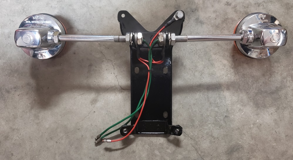
August 16, 2020 Too many visitors, too many phone calls! I didn't finish the
wiring today, but it is all tested. Just
needs the final wrapping and installation.
The headlight socket gave me fits. The beam unit, which is mostly in great shape
had white corrosion where the bulb sits
and it was insulating the bulb from ground. I have new sockets, but the originals
are much better made so I cleaned up
the original.
The ignition switch was not reliably snapping into the four positions � that's
all cleaned up and working fine now.
The foot brake switch I installed tested good after I cleaned it up and installed
it � now it has quit working reliably
so I'll change it.
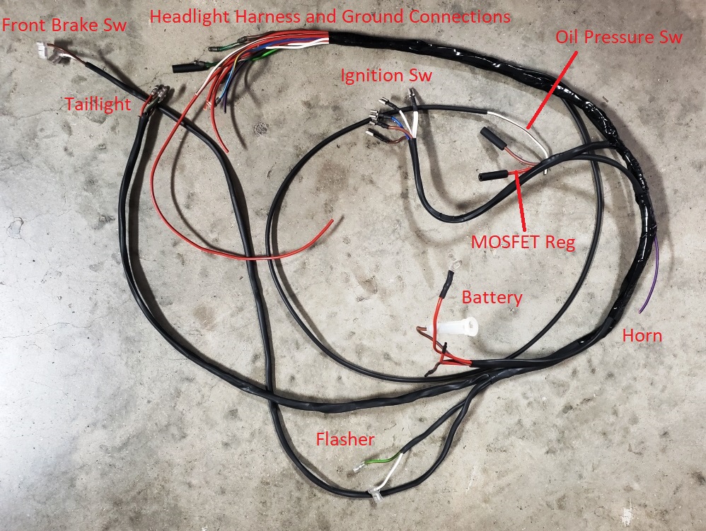
August 17, 2020 The picture shows the harness ready for final installation.
Some of the connections to the
headlight harness, engine ground, oil pressure switch, horn and coil ground need
to be cut to length and terminated.
It's best to leave them until the end as minor changes in where they end up
happen when the harness is wrapped. It's
a
simple job from here since everything is tested. The headlight is closed up and
the turn signals are all aligned as
well.
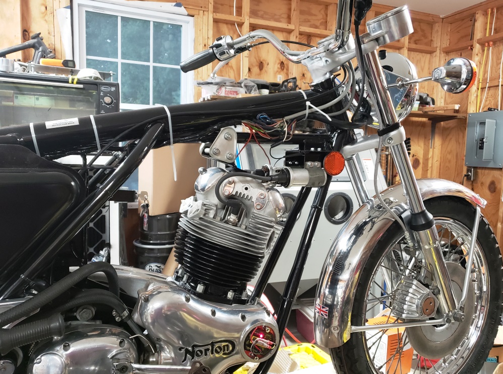
August 19, 2020 Progress has been slow the last few days as I'm having
swelling trouble with my legs again. Still,
I'm getting there. The Tri-Spark ignition is installed, tested and statically
timed. The tail light, brake switches,
and
headlight are all done. I forgot to install the instrument lights so I still have
to do that. I ran out of covers for
the master switch, so it is only temporarily connected for testing, and the oil
pressure switch is not installed yet so
its wire isn't connected. Also, I'm out of long black cable ties so the
white ones are temporary until I get black
ones.
Next is the carbs. I would push hard to use new premier carbs, but Amal hasn't
been able to supply the 32mm carbs for
quite a while and I'm completely sold out. So,. I'll have to make do with
the carbs that came with the bike.
August 20, 2020 I'm 70 and have all my hair - no bald spots. Good thing
because I'm about to rip it out! I'll
whine about that in a minute.
I installed the instrument lights and finalized the coil wiring today. Then I tried
to bolt down the taillight. I talked
earlier about the rear fender being somewhat out of shape, probably due to the old
frame. That's cropped up again. The
three holes for the fiberglass part of the taillight are not in the right place
by a little. I'll have to remove the
taillight and elongate the slots a little � not a big deal, just fiddly.
The last thing I needed to wire was the Tri-Spark rectifier/regulator. That was
no big deal. Then I decided to check the
leakage current to it and to a PODtronics POD-1-HP out of curiosity . Nothing was
working. It turns out that I forgot a
splice in the brown/blue wire � Grrrrrrrrrrrrrrrrrrr! Now I have to take the harness
that was finished and installed
back out of the bike, unwrap it, make the splice, and as my wife used to say �Lick
my calf over'. If you don't
understand that saying � think about a newborn calf and it's mother's first
job after giving birth! The only good
news
is that I wanted to do that test which has nothing actually to do with this bike
but it did let me find the problem
instead of having the bike done and it not charging.
August 21, 2020 The harness is fixed and reinstalled. So is the taillight
and the rear brake switch is replaced.
I end got black zip ties and velcro wraps today so that's done. Checked
everything and all was well until the
very
last check! The front brake switch quit working. When I first tested
it, it didn't work. There was
a
lot of rust in it so I cleaned it out and retested and it seemed fine. I even
had the PITA cover on it. Now
I'll have to change it. At least I have some and they're not expensive.
The annoying part is having
to
re-bleed the brake.
August 22, 2020 So, two wrongs can make a right! More on that after the first
picture. The front brake switch is
replaced and the brake re-bled. The wiring is all strapped down. There are a few
outstanding things related to wiring. I
had to order a master switch cover. I have to line the battery box with rubber and
make one of my battery hold-downs.
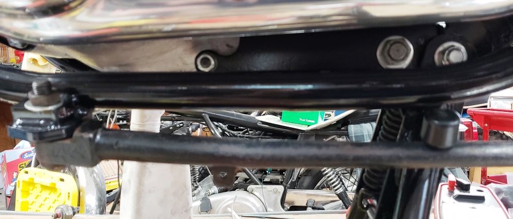
Besides being powder coated, this frame needed the side stand lug replaced. The
power coater took care of that and did a
very good, but not perfect, job. He had the template from OldBritts and he had my
good frame to reference. Still,
without a factory jig, it is almost impossible to do perfectly.
The side stand itself also had problems. The bushing is worn and should be replaced
but I don't have one right now �
I
sure wish I had a lathe � I could ream the hole in the stand and make a bushing
to fit perfectly! The end where you push
it down with your toe was pointing in the wrong direction. And, the main shaft had
been beat on to straighten more than
normal.
Sorry the pictures all turned out fuzzy.
In the first one you can just make out that the stop is below the frame so it's
doing nothing. The lug is slightly
twisted clockwise � one of the wrongs. But it is slightly pointed too far down �
the second wrong. But add them together
with me hammering what seems like forever, and the stand should work fine. I measured
the 850 I have with it on the
center stand and the side stand out. It was 4.5' to the top of the crook where
the bottom of the side stand sits on the
ground. This one measures 4.5' in the middle of it's up and down slop (needs
a bushing). I tried the new stand from
that
bike on this one and it measured the same. So, those two wrongs canceled. Still,
the bumper only minimally stops on the
frame and I don't dare bend the stand anymore because it would make the bike
lean over too much. More on that shortly.
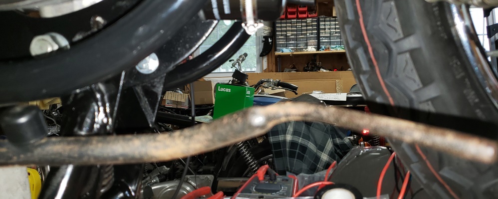
In the second picture you can see the bumper problem (before I beat it into submission)
from a different angle and you
can see the end pointing in the wrong direction.
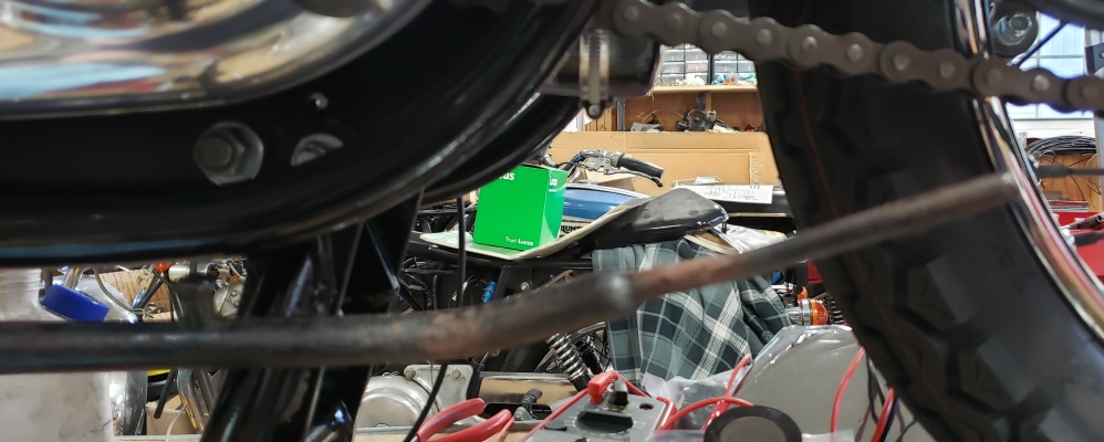
In the third picture you can see the end of the stand now pointing in the right
direction.
In the last picture, you can see the final solution. The bumper will actually work
by itself, but for a little better
cushion, I wrapped the frame tube with three rounds of thick rubber tape. If that
holds up it will be fine. If not, some
sort of metal clamp around the tube would work.
The stand has now been blasted and painted � it will go on tomorrow and hopefully
I'll be back on track.
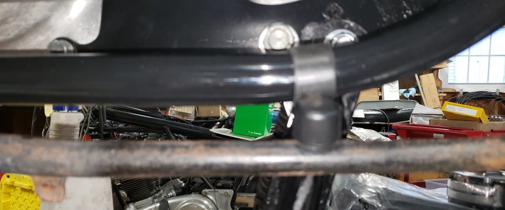
August 23, 2020 Installed the exhaust on the drive side today. Of course, I ran
into trouble. We swapped the exhaust
between this bike and the owner's 850. This bike had cross-over pipes so the
exhaust nuts were the short version. The
pipes I installed need the long version. So, I went through my junk and found a
pair. These exhausts are temporary so
that will be fine. In fact, the junk ones I found look better than the ones the
bike came with. The side stand is
installed too - had to use a new spring as the old one was stretched. Fiddled with
the rear brake cable quite a bit �
always do on a Norton � bad design and the routing is critical. I haven't done
the drive side exhaust yet since I and
doing some R&D on a rocker feed line and the exhaust would be in the way.
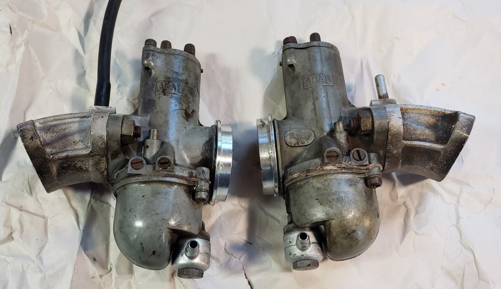
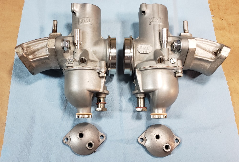
Then I started on the carbs. The first picture shows what I started with. They are
R932/19 and L932/20 which is correct
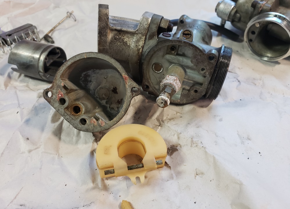
for a Combat so they are probably original. That's where the good ends! The
second and third pictures show what the
insides look like. The bowls, jets, and jet holders and unusable. Fortunately, I
went through my old carbs and found
usable bowls and jet holders. The main jets are wrong anyway as they are supposed
to be 220s and are 240s. The needles
are not good, the float needles are plastic as are the floats. Most importantly,
the slides are supposed to be 3 cutaway
and one was 4 and the other 5! So, Amal Major Repair Kits with StayUp floats will
be used, new ticklers installed, new
drain plugs, and new slides. They won't be new and I would push to install Premiers,
but they are unavailable and have
been for a while.
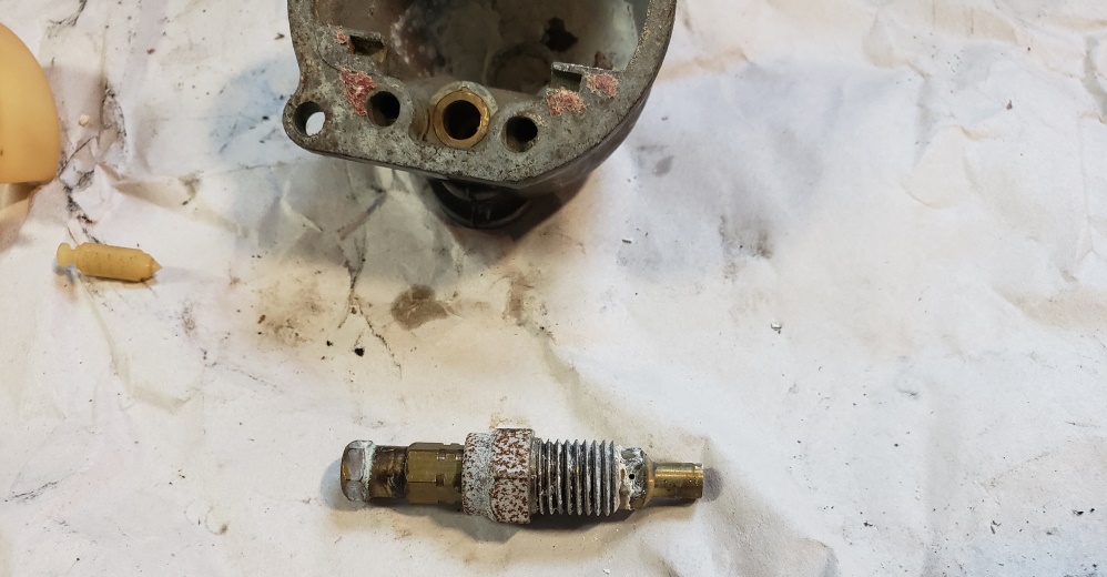
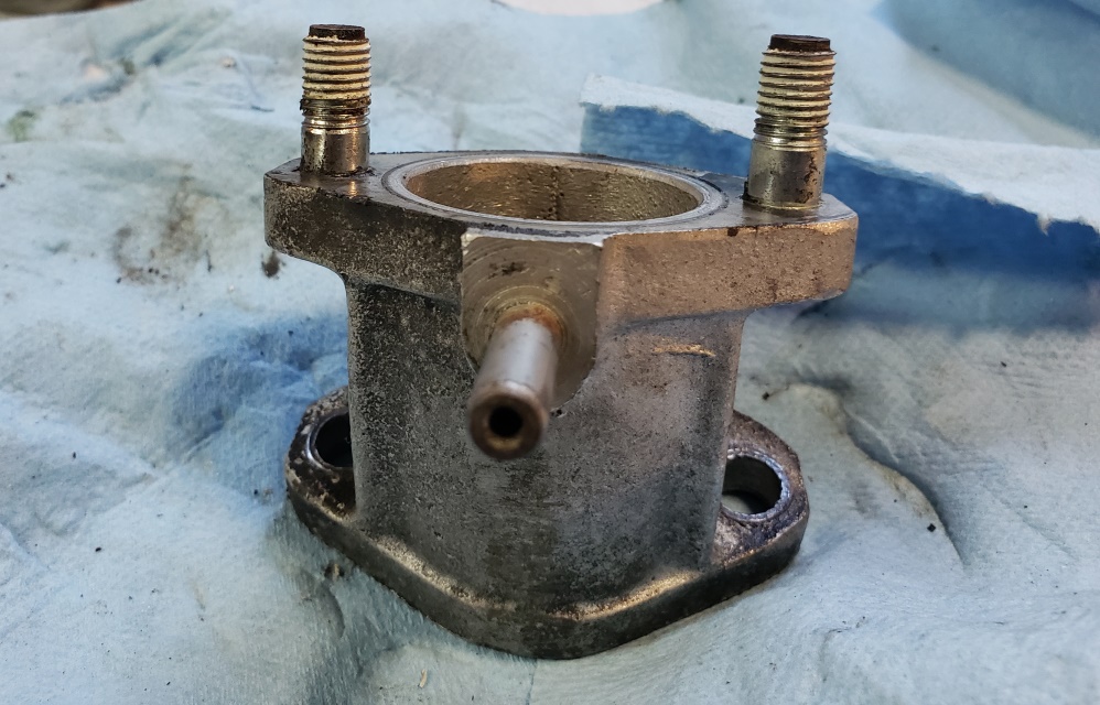
The true annoyance is shown in the fourth picture. Someone used some sort of thread
sealer on the mounting nuts. In the
first carb, the studs came out of the manifolds. On the second, I heated them with
a torch and got the nuts off.
Loctite on the threads into the manifolds is a good idea � on the nuts � a terrible
idea! The carbs and manifolds have
been cleaned. The bowls and mounting flanges have been flattened. Tomorrow,
I can build them.
August 24, 2020 The carbs came out nice, even if I do say so myself!
They were very clogged so it took a
while to get the bodies clean internally. Almost all the internal parts are
new. The bodies show only slight
wear to they should be good for a couple of years. The cables are next and
I'm almost afraid to look at them.
Hopefully they are usable so I don't have to make them!
August 25, 2020 Well, I was right to be afraid to look at the cables!
The short cables are all choke cables!
Of course, I didn' notice that until I had them in the carbs and they wouldn't
work - the "stick out"
is too long.
I can remake them shorter, but more importantly, the slide is jamming in the left
carb. So, I have to do one of my
most hated things on a Norton, and remove that carb. It may have been over
tightened at some point, or ???
The old slide didn't stick so possibly the new slide is bad, but if so, it will
be the first I've seen and I've
sold
hundreds. I'll try another before removing the carb. Hopefully,
I have another body if this one is bad.
Norton's are annoying anyway. Having the splitter and the cable length
adjustment on top of the carb is a PITA.
On Triumph, you use a dual-pull twist grip and two one-piece cables. The adjustment
is near the twist grip so it's
simple to sync the carbs with the tank on.
August 26, 2020 I'm starting to feel like I'm whining with every report
:-o. The carb saga�
I tried another slide in the left carb and it stuck too; so, off came the carb for
inspection. I couldn't see anything
wrong, but the slide had one rub mark so I knew it was binding there only.
Since I have a 72 Combat in boxes, I dug though the boxes until I found the carbs.
I cleaned up and checked the right
one � it was fine and not too worn. It did have a plugged needle jet passage from
mud daubers but that wasn't too hard
to clear. However, when I tried to put the bowl on, I realized that one of the two
screw holes was stripped � that carb
is unusable. Then I went through my boxes of carbs and although I found plenty of
bodies that would work, none of them
were marked 932/20. That doesn't technically matter but the owner wanted to
use the originals.
Next came two hours with a fine file cleaning up the high spot in the carb adjacent
to the tickler. Once the slide was
able to move correctly, I installed the carb and worked on the cables - that went
OK.
OK, home free? No way in hell! Put everything together and the twist grip would
not twist! The tensioner was more rust
than metal and came off the screw. It's not needed anyway do I removed it and
the screw and reinstalled.
OK, home free? No way in hell! Now the left carb worked fine but the right slide
was dragging the choke up with it and
jamming. So, took the right slide/choke out, changed the choke slider and put it
back together. Finally, the throttle
works. Then I cleaned up and went to install the choke lever � can't find the
mounting screws � gave up for the day
:-(
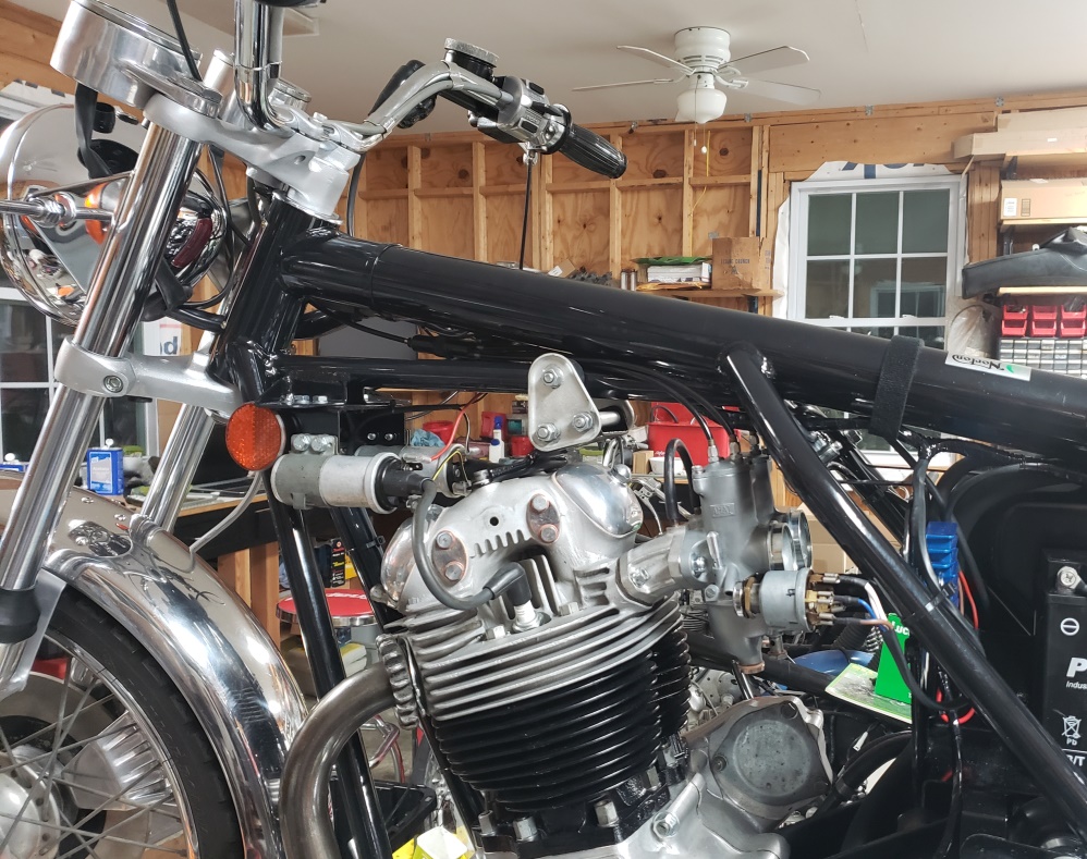
August 27, 2020 I was very popular today! Every time I got my hands
dirty someone called me. I should
have not answered! I did get the carbs statically synced and then I went to
work on my rear brake cable R&D
project. I'll write that up here later - too tired right now. I
did start a new thread on Access Norton about it.
Here are the pictures. The first picture shows the problem. That's a brand
new cable from AN and it's already
scuffed just by installing it on this bike is being built and has never sat on the
rear wheel.
The factory large Z-Plate spacer (06.0472) is approx. 35/64" thick and the
two smaller spacers are 5/8" thick.
I used
the same ID and OD for each but 5/8" thick for the large spacer and 3/4"
thick for the small spacers. This spaces
the
silencer mounting out a little over 1/8" since the large spacers is only 5/64"
thicker and the other two are 1/8"
thicker.
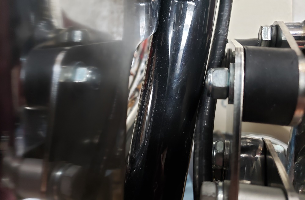
The second picture shows the result. There's now plenty of clearance to the
silencer mount. The cable touches the swing
arm, but I will tie wrap it to the swing arm at that point so there will be no rubbing.
The cable lies nicely between
the various nuts and won't hit them as the swing arm moves.
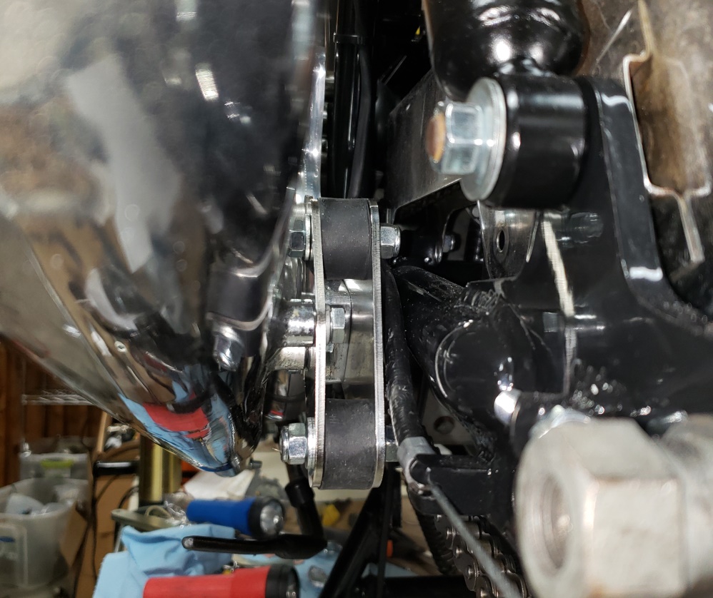
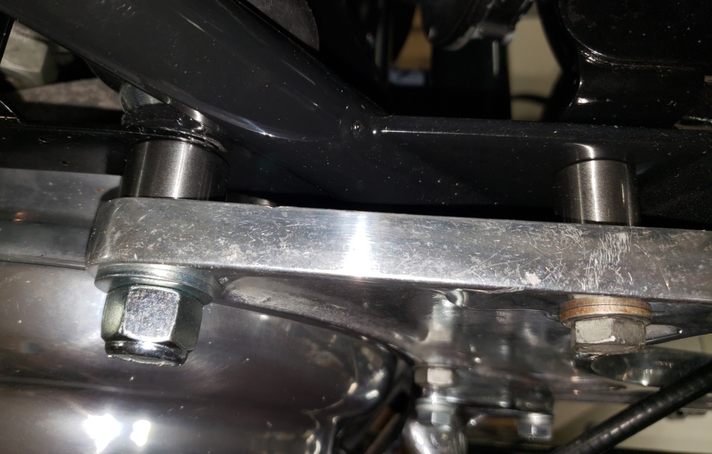
The third picture is another view. The fourth picture just shows the spacers in
place. Besides the spacers, you need two
3/8" UNF x 2-1/4" bolts. The standard bolts (14.0235) are 2" long
and are a little short. The 1/2" rear
mount stud is
long enough for the new spacer. I still need to get the longer bolts - the
standard ones are used right now.
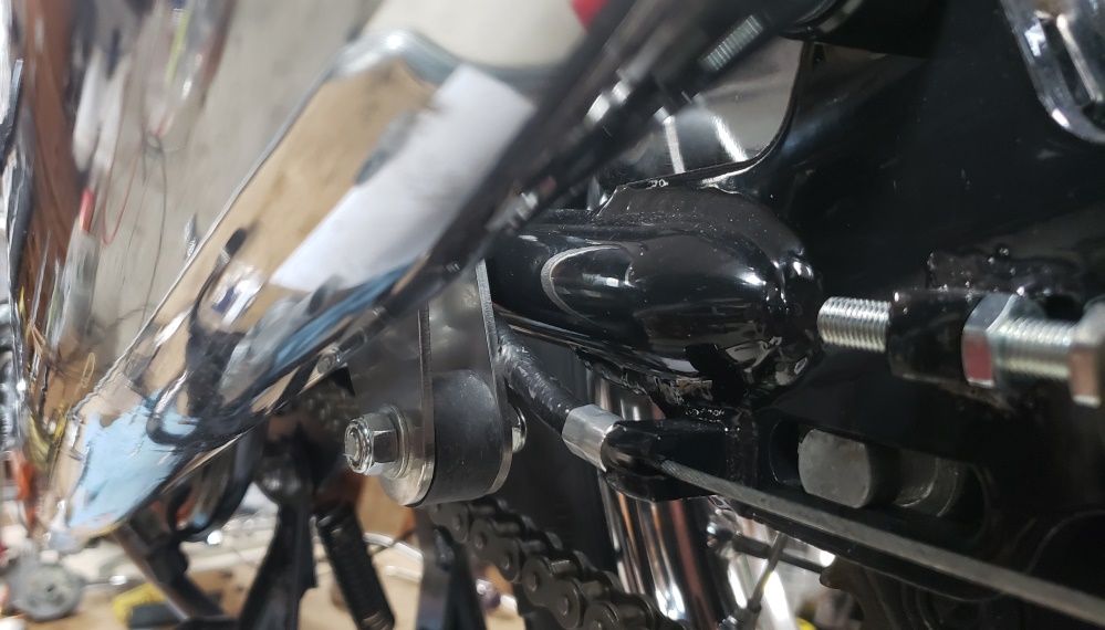
August 28, 2020 Found the screws for the choke lever and installed and adjust
that. Got the master switch
cover today so I installed that and retested. Grrrrrrrrrrrr! The tail
light was on no matter how you turned
the switch, including off. Took the switch back off and tested - nothing was
right. Would have installed a
new one - I have four in stock - they are all junk! So, I set about fixing
the one that came with the bike.
It's working again. One of the four pressure springs got stuck and got
out of position shorting the switch
out. It's good for now, but I wouldn't trust it from long. I'm
trying to find a source of a good
switch.
I haven't tried AN because they are very expensive and I think they are using
genuine Lucas (Wassell) and I can get
them
for much less there myself.
My rocker oil feed R&D project is behind waiting so I'll install the standard
line. I'm hoping to start
this
bike the weekend!
August 29, 2020 Made a lot of steps forward today and none backwards for a
change. Make an expensive mistake
though - keep the last sentence from yesterday in mind and I'll get to the mistake.
Start today looking for the 3/8" x 2-1/4" bolts I needed. I didn't
have any. Checked the Make
Do Po site and
not only do that carry them (according to the site) but the Annandale store had
19 in stock. Of course, the 38"
UNF drawer was empty - they had no 3/8" UNF and no place for the one I needed.
I figured maybe the much bigger
store in Bailey's Crossroads would have them so I drove there. At lest
their 3/8" UNF draw wsn't empty
but there
was no place for 2-1/4". The did have 2-1/2" so I got two of those
and cut them down. Then the real
fun
began! If you've never changed a bottom drive-side Z-Plate bolt - do what
you can to never have to unless the
bike
i apart! It's one of those PITAs on a Norton.
Now for the mistake. The guy helping with my rocker feed line R&D project
needed a sample of the OEM nylon lines.
The 72 Combat I have in boxes came with a new one. Since I don;t use them
on my builds, I sent the one that came
with this bike and planned to use the new one here. I have no idea where the
previous owner got them, but the
cross-over tube is about 3" too short and it cannot be used. So, to make
this move alone, I installed the last
stainless line set I have from AN and I certainly cannot charge th owner for that
mistake!
When my grandson was here helping me, he blasted a bunch of part. The plan
was that when he came back I would
teach him to powder coat. He got too busy being a teenager and getting ready
to go off to college (in other words,
he slept a lot) and never came back. I'll have to powder coat it tomorrow
so I can installed the air cleaner.
Here's what I can think of that left:
- Speedo cable - I only took a quick look. It seems in terrible shape.
I hope I have a decent used one since I don't have any in stock right now.
- Tach cable - I haven't looked, but I should have one in stock if it's
bad.
- Powder coat the front of the air cleaner and install (maybe the 2nd hardest thing
on a Norton)
- Make and power coat a battery hold down.
- Install the license plate
- I realized today that my rider has a good new master switch so I'll put that
one on this bike. I haven't
gotten back to the work I was doing on my rider for about two years so it's
no big deal.
- There are a few things that must be once the bike is on the ground.
- After bouncing the front end up
and down, tighten the pinch bolt (see the tag hanging from it so I don't forget)
- Fill the oil tank and check for leaks
- Double-check the rear chain with someone sitting on the bike.
- Strobe the timing.
- Set the idle speed and mixture
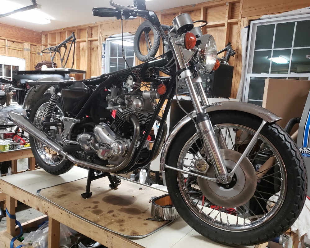
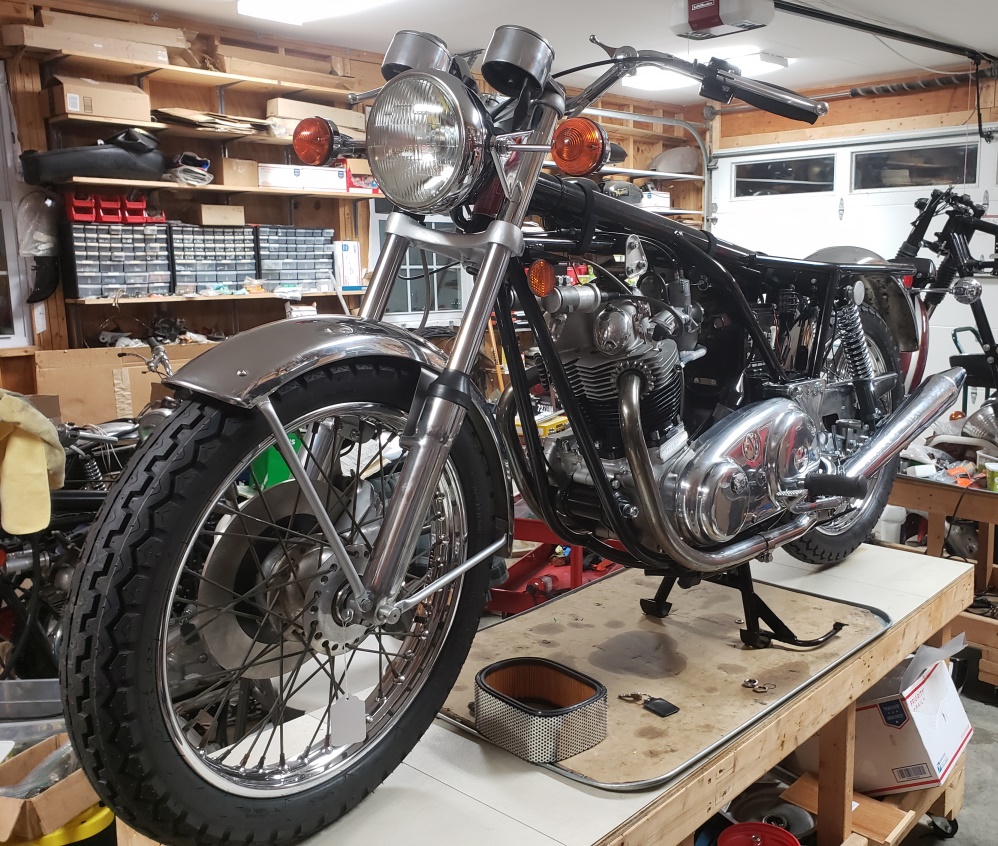
August 30, 2020 This project started March 1, 2020. We decided to change the frame
early on so I striped the bike down
and worked on the engine and gearbox. The frame came back from the powder coater
June 28, 2020. So, although I've been
working on it for five months, the actual building has been just over two months.
Big events to today! It came off the table and the owner and I installed the tank,
finished up a few things, and fired
it up. Then he took it out for a ride. That went pretty well. He reported the engine
reving when the clutch is pulled �
I'll take it out myself so I can understand that. Also, I guess I didn't
tighten the headlight enough because that
came
loose.
At any rate, it started very easily and idles well. I ran out of time to make the
battery hold down so that's
outstanding along with final tuning.
The bike needs a proper shakedown ride. It hasn't been ridden far enough
to get it completely warmed up and
probably hasn't been above 60 mph or in 4th gear. The one burst I gave
it took it to 60 without hesitation but
I
was in a 35 zone riding without the registration so I was about to do that long!
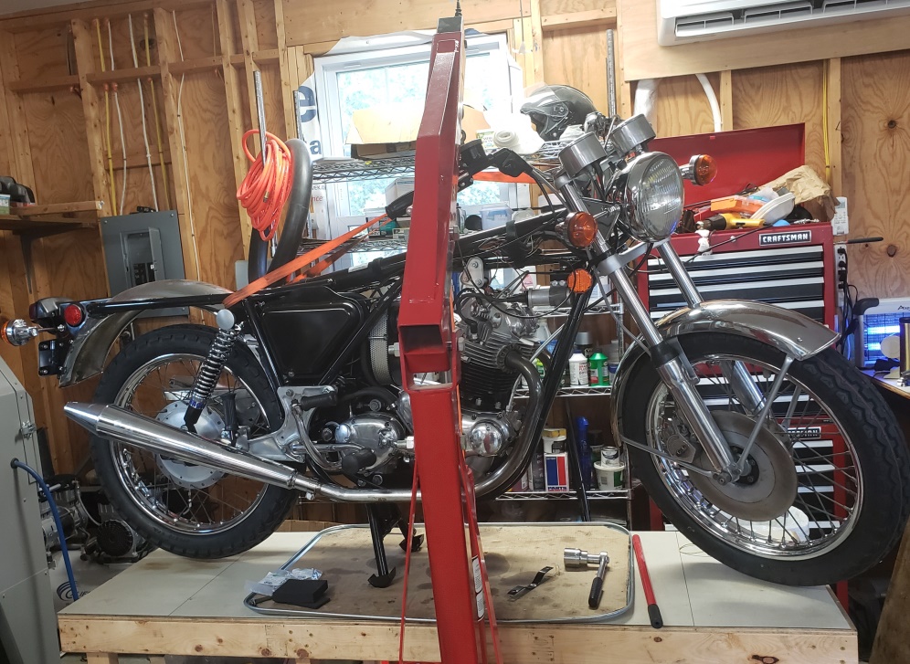
September 5, 2020 Will this never end?
The owner reminded me that he likes the speedo on the left which is Norton standard.
I guess I got confused since
it's on the right on all my bikes (Triumph standard). I switched them
today.
When we first started it, the tach
didn't work, but then it started working while he rode. It's still
works, but the speedo has stopped.
It's
probably just sticky but I still have to check it out - the cable is a mess which
I repaired and is a little short for
the speedo on the left, but its should work.
The clutch/switch console won't tighten enough to be stable - still
have to fix that. I thought he didn't have a tach cable but I found one
in his parts box so I swapped it for the
new one I installed since it is in decent shape. I re-aligned the headlight
and turn signals and tightened it
better.
I took the bike out (very hard for me by myself) and it started first kick and idled
well. So, off I went to see
what he meant about it idling fast with the clutch pulled. As soon as I got
above 3000 RPM, it wouldn't go below
3000 RPM! One or both slides are sticking or the junction box is getting caught.
I've had the junction box
do that before and as much time as I spent on the carbs, I'm having trouble
believing that the slides are the problem.
So, once I recover from the effort of getting the bike out of the shop and back
in, I'll get into that. I keep
saying that I'll never do it the Norton way again and then did once again.
It is so much better to have a twin
pull twist grip and cable adjusters in-line near the twist grip like on Triumphs.
It's pretty ridiculous to have
to
take the tank off to adjust the cables and slides!
The good news is that it runs strong and handles well.
September 6, 2020 I don't want to jinx myself, but I might be done!
The speedo is not working but will probably start working - there's nothing
wrong with the drive or cable.
The loose clutch/switch console is fixed - added rubber. I guess the handlebars
are slightly small because I've never had this before.
In previous pictures, you'll see the standard air filter and surround beneath
the bike. I could not get it in
by myself and had to touch up the cradle paint scratch from trying. You'll
notice in the next picture an air filter
installed. This one is narrower, installs easily, and doesn't cause damage
on the way in. I took if form
the
850 I have for sale so that bike is off the market until I can replace it.
It turns out that the left carb slide was sticking and the cable was popping out
of the junction and catching - makes no
sense
because it wasn't
when I put it in. There was a little grit that was causing it - it must have
been in the air cleaner when I
installed it. Anyway, it all works now and was fine on a short test ride (too
worn out to go far).
I'm getting pretty good at making battery hold downs! Beneath, to the
right, and behind the battery is self-stick
high density foam and the hold down bracket it lined with it as well.
The second picture shows the left-side panel/toolbox installed. Actually,
everything is installed and it's done
except for a better shakedown ride and
possibly touching up the idle.
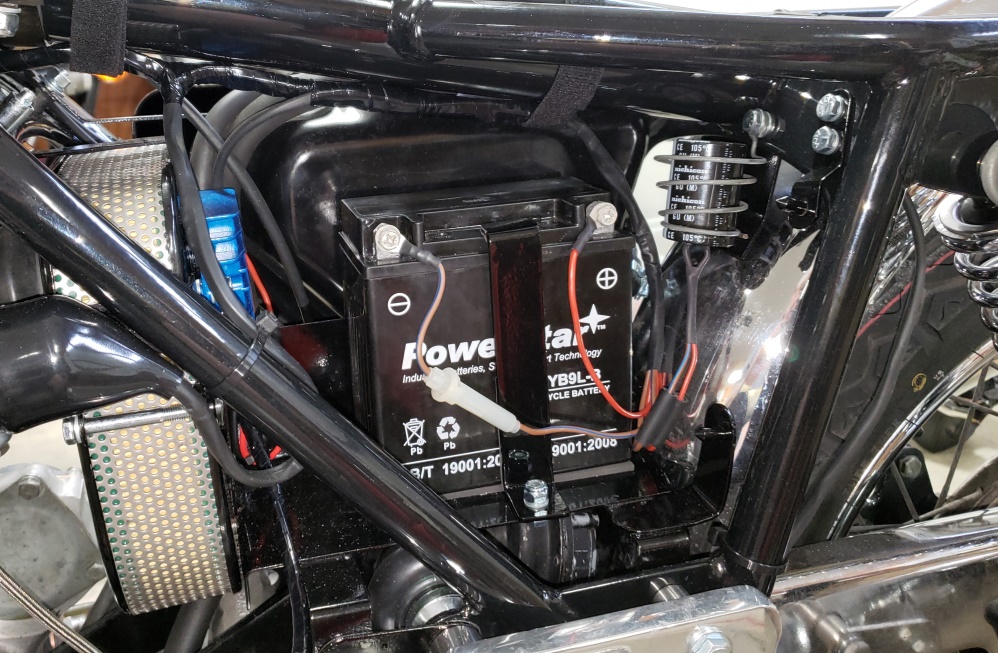
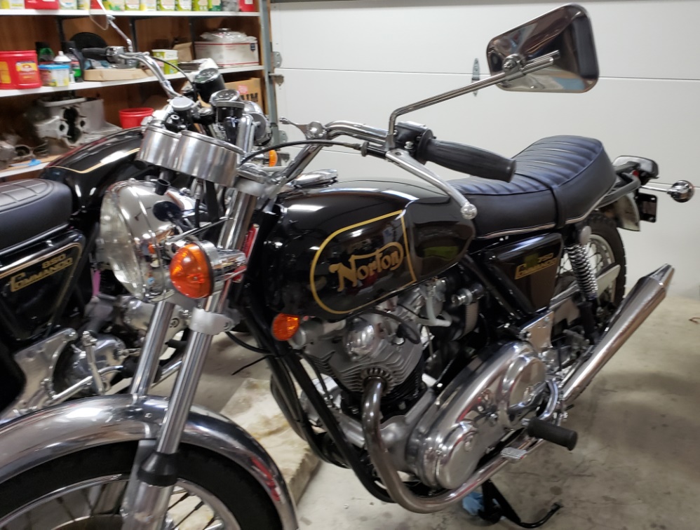
September 7, 2020 It's done! The speedo still doesn't work but
the odometer does so it probably has
a broken
wire inside. This can be a winter project - the owner can just send it off
to Vintage British Cables, and it will
come back like new and the odometer reading can be maintained.
I noticed that gas was barely flowing with one petcock open - the air hole in the
gas cap was clogged.
It starts first kick and idles - important if you watch my gyrations so get on.
I stand on the right side, kick
with my right leg, walk around to the left side and force my right leg over - all
while on the center stand.
Getting off is even worse - I have to get off on the right side, balance the bike
up as I walk around behind it and put
the center stand down. I had one very scary moment. I was wearing sneakers
and I have very big feet.
My foot got stuck under the gearshift when I started to get off the bike.
I took it out for a ride keeping in mind that it must be broken in (new cam, pistons,
rings, and brakes). It runs
very well. I got up to 6000 rpm once in 3rd gear and shifted to 4th, but slowed
down right away. It pulled
strong all the way there. The idle could be better, but it's the best
I can do with these carbs - shouldn't
be
idling and old air-cooled bike anyway.
I stopped at a gas station and filled up - it started first kick while hot, of course,
no tickle.
The owner put the correct tires on the bike - Dunlop TT100s. I'm used
to Avon Roadrunners now and they feel very
different when leaning into corners. The Avon's have smoother grip in
corners, but the Dunlops are probably better
in the rain and definitely better in the grass. I used Dunlop K81 or TT100
for a very long time so I'm certainly
not against them.
If you've been reading along and have the idea that I'm crazy and will rebuild
your bike for you - you'll have
to give
me time to finish some my projects and to forget about this, the other frame change,
the "just get it going",
and the 650SS I've done this year. I have 14 bikes to repair/build/finish
building that I can remember right now.
The 850 Roadster I finished last year is still sitting here needing a few minutes
of work and then to be listed for
sale. If you want a beautiful 74 850 in black or red just stop by with a check
for $13,000 which is a steal.
May 18, 2025
Surprise, surprise! The owner took First Place Norton at the Classic Motorcycle
Day in Maryland today!
This bike was modeled after my 2019 win at the same show. 1972 Norton 750 Commando Rebuild
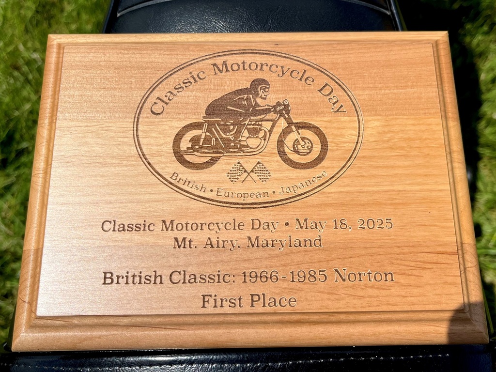
|


|
Copyright © 2003-2026
Greg Marsh Enterprises
8116 Arlington Blvd. #171, Falls Church, VA 22042
(703) 200-4025 marshg@gregmarsh.com
|
|