|
|
 | Wednesday, July 22, 2026 |
Update 7/27/20 I've made several updates in this first part - from the entry June 20, 2018 to the end, nothing has
changed. This page was called originally Norton Wiring and was created while I wired the 1972 Norton Commando Combat. Several people
asked for details that I didn't record so I promised to provide more details on the next rebuild - See: 1974 Norton Wiring
It might sound strange, but I like wiring Vintage British Motorcycles! But, I also like to update them and eliminate some
of the problem areas and potential for having to push the bike - way too old to be pushing motorcycles!
I'm just starting on the wiring for a 1972 Norton Commando Combat so I'm going to document how I do it here.
For the bike build itself, look here. Here are the parameters I'll follow:
- Use standard 18ga wire and standard colors. Where there is any deviation, I will spell it out. The modern wire is
the same gage and same number of strands, but the insulation is thinner so it is easier to run. On most bikes, I
take apart old harnesses and reuse the wire, but almost all Norton wires are short due to the connection under the tank,
so I'll mostly be using new wire. When using old wire it is important to make sure it is flexible along the
entire length. Wire can become "work hardened" and can break at hard spots.
- Replace the points and condensers with a Tri-Spark ignition.
- Replace the Zener Diode and Bridge Rectifier with a Tri-Spark VR-0030 (MOSFET Rectifier/Regulator). I used to use
the PODtronics POD-1P-HP and Tri-Spark noise filter, but the last one I installed caused so much noise that the bike
would not run correctly so I've stopped using them.
- Replace the Warning Light Assimilator with an oil pressure switch.
- Eliminate connectors wherever possible/reasonable. Standard Norton wiring has LOTS of connectors under the tank.
This was done so they could use one rear harness for multiple bikes (standard, police, etc.) The only thing some might
consider good is that reduces the wiring in the headlight shell. It makes handlebar wiring a mess, especially when
changing the size of the bars.
- This bike needed a new headlight shell so I opted for one with three grommet holes on the bottom - not a requirement,
but it is nicer when making most connections in the headlight shell.
- The original horn for this bike was not salvageable so I bought a new one from Andover Norton. It is smaller, made of
plastic, and mounts differently. I decided to mount it and the PODtronics in the battery area on the back of the rear air
cleaner housing. So, the horn wiring will be very different from standard � keep that in mind if you use my ideas to wire!
Also, the 850 MK1A/MK2A air cleaners are different so these cannot be mounted in the same place. Mounting these in
the area means that the standard battery hold down won't work so I'll have to figure out an alternative.
- The frame is not a part of the ground on a Norton due to the isolastic engine mounts! I modify the rear turn signals
to have a ground wire and I add a ground wire for the taillight. All three connect to a ground wire that runs the
length of the bike - this will become clear later. On other Vintage British bikes, the frame is a good ground so this
is not an issue.
- I use a combination of sleeving, vinyl harness wrap, and heat shrink tubing. The hardness wrap is NOT electrical
tape - it has no adhesive and never gets sticky.
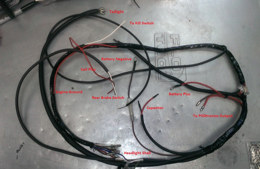
June 30, 2018 So, here we go step by step. Often, each wire will be run but not terminated until all wires are run
and loosely bound unless otherwise stated. Leave a little extra on the ends. There will be solder splices inside
the harness so it is important to get the locations figured out as we go.
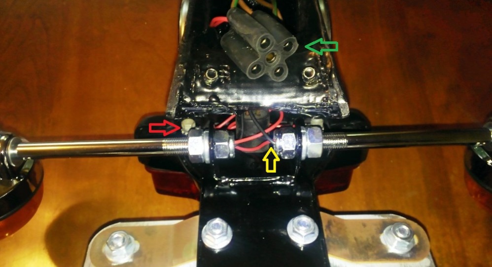
Starting at the taillight assembly. See the yellow arrow - you'll see a black and a red wire coming from each
turn signal. If these were original turn signals, they would have a green wire rather than the black wire. I
add the red wire by taking the signal apart and soldering the red wire to the outside of the socket. Notice the red
arrow. These bolts go to the ground of the taillight. I terminate the turn signal wires and one more wire to
go under those bolts. The third wire goes to the five-way connector pointed to by the green arrow. That connector
has the taillight, brake light, two turn signals, and the ground wires.
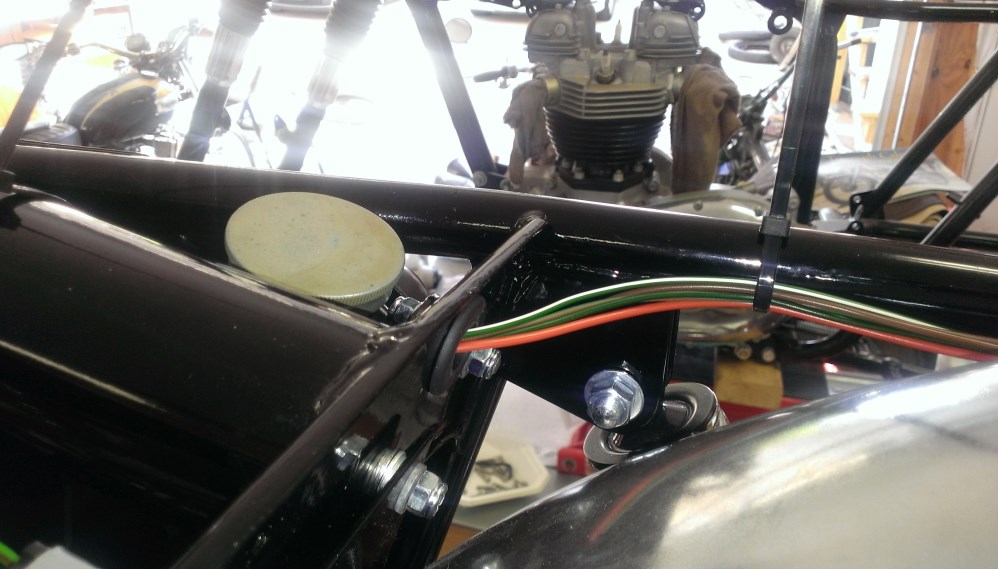
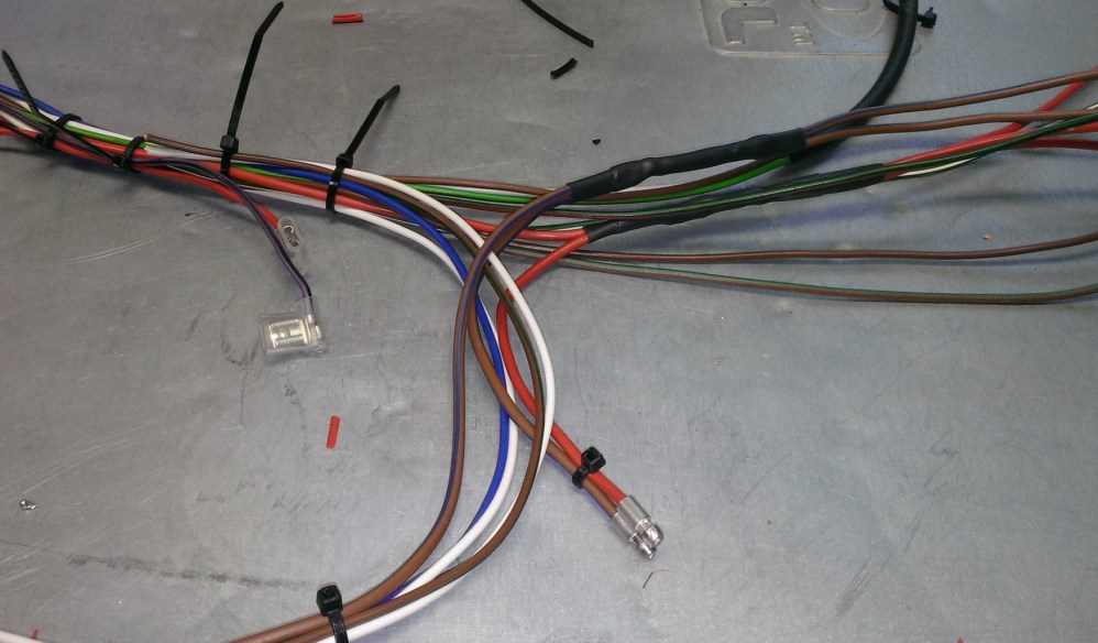
Terminate one end of the following wires with a bullet: Green/White, Green/Red, Brown/Green, Brown, and a 14ga Red and run
those five wires to the headlight shell. They pass through the grommet on either side of the oil tank and should run
on the right side of the steering head and into the center grommet hole in the bottom of the headlight shell. It's tempting
to run the brown wire straight to the front brake switch, but this will lock-in the handlebar size so it's better to
have a cable from the front brake switch to the headlight shell and make the connection there.
Since the taillight assembly must be taken off to connect the harness, I temporarily connect the wires, put the taillight
on, and then secure the harness wires to the frame tube as an anchor point to start making the harness. Then I can
remove the taillight assembly and set it aside.
July 4, 2018 The wires above are run, but it is so hot in Virginia that it's not possible to work in the shop right
now. The heat index was 113 yesterday at 3pm.
July 7, 2018 The 4th of July holiday is over and the weather is very nice today so I'm back to wiring. Norton
deviates somewhat from the others in the headlight wiring. They used Blue/Yellow to go from the Master Switch to the
Headlight switch, Blue to go from the headlight switch to the right hand handlebar switch which is also a Blue wire.
I'm using Blue rather than Blue/Yellow so it is consistent from the Master Switch to the handlebar console.
Run a Blue wire from the master switch to the headlight switch.
Run a Light Green/Brown wire from the flasher to the headlight shell.
Run a White wire from the rear brake pedal to the flasher and run a Brown wire with that White wire in a PVC sleeve to the
area of the harness above the battery - a splice will be made there to the brown wire running the length of the bike.
Terminate the White wire plus another White wire in an insulated right angle spade connector - the second White wire goes
to the headlight shell. Use a short piece of 5mm PVC sleeving to cover the Brown, White, and Light Green/Brown wires
from near the flasher to where they will join the harness above the battery. Use a piece of 5mm PVC sleeving to protect
the Brown and White wires going to the rear brake pedal.
Run a separate White wire from the Master Switch to the headlight shell and put a Sharpie mark on it so it can be identified.
Run a short White wire from the Master Switch to the area above the battery - this will be spliced into the White wire from
the flasher.
Run a Brown/Green from the Master Switch to the area above the battery - this will be spliced into the Brown/Green running
the length of the bike.
Run a Brown/Blue 14ga wire from the Master Switch to the area of the capacitor. Terminate one end of a Brown/Blue 14ga wire
with a bullet and run it near the left side of the battery and the other end to the area near the capacitor. In other words,
there will be four wire ends: one to the master switch, one with a bullet that will go to the Black wire of the PODtronics,
one unterminated that will go to the negative of the capacitor, and one that will eventually go to the fuse. You'll
see shortly how these are combined into one circuit.
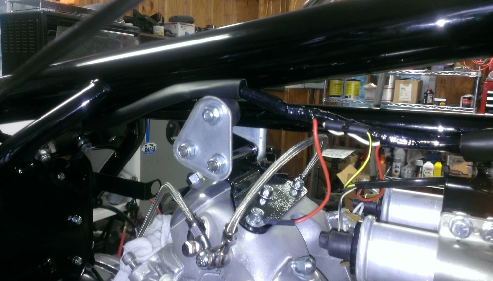
Terminate one end of a Purple/Black wire with a right angle insulated spade terminal and attach to the horn. Run the
other end to the headlight shell.
Terminate one end of a Red 14ga wire with a bullet and run it near the left side of the battery and the other end to the
area near the capacitor. Terminate one end of a Red wire with a right angle insulated spade terminal and attach to
the horn. Run the other to the area near the capacitor - make sure this wire can reach the left side of the battery.
Run another Red 14ga wire from the area above the battery to the area near the capacitor - make sure this wire can reach
the left-side of the battery.
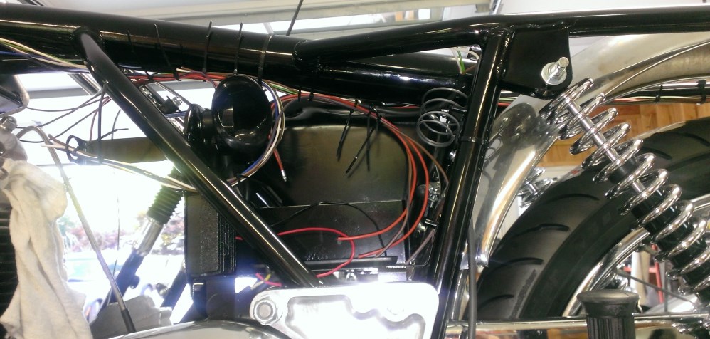
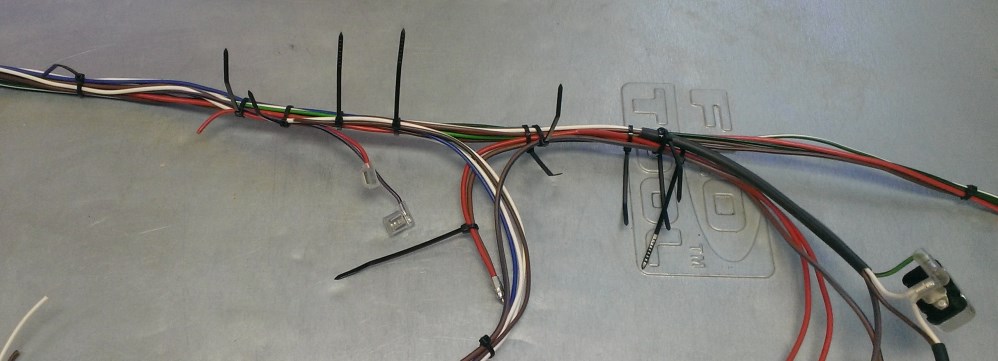
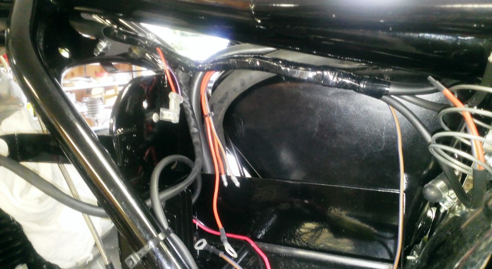
Route all wires in the battery area nicely and use plenty of tie wraps to make sure they stay in place. Be sure you
know where the wires will exit the harness. Notice the location of the horn, PODtronics, and capacitor spring. The horn
location is very different from standard!
Remove the harness from the bike and move to the workbench.
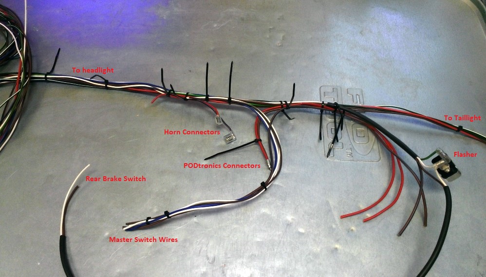
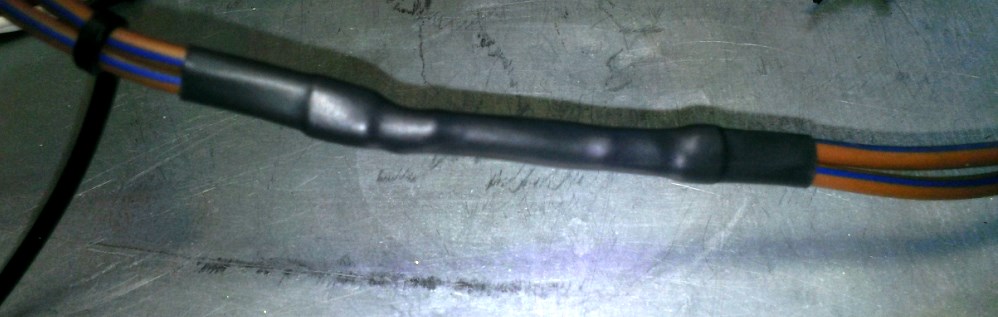
The Brown/Blue wires need to be spliced. First, isolate them so you know where the splices should go. I cover
the splices with heat shrink extended about 1/4" past the splices and then put on another layer that extends about
1/2" past the splices.
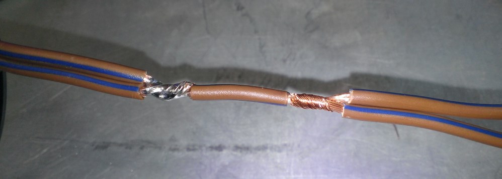
Similarly, the Red wires need to be spliced. Here, most of the splicing is done. The Red wires are all spliced
into the Red wire that runs from the taillight to the headlight. There are two more splices to be made, but first,
the harness needs to go back in the bike and be readjusted - they always move some when slicing.
July 9, 2018 Almost forgot my White/Brown wire for the Oil Pressure switch and realized that I had a second Brown wire that
wan't needed going to the headlight shell. Both because once everything is run to where it goes, I recheck everything.
I'm not bothering with the power socket. If you want to wire one in, then the wires need to be spliced in now.
The only wires that exits the harness under the tank is the White/Yellow wire from the headlight shell that connects to
the kill switch, a Red wire for the coil ground, and a Red 14ga engine ground. Both of these Red wires are spliced
into the 14ga wire that runs the length of the bike.
July 11, 2018 It's been hot! I lost some pictures. The harness is ready to go in the bike for keeps.
I used a length of PDV sheathing for the wires from the battery area back and a piece for the master switch wire.
I've vinyl wrapped the harness and put most cable ends on. I'll get new pictures tomorrow of the harness off
and on the bike. Once it's on the bike, it will get a full system test before I finalize tying it down.
July 12, 2018 The harness is complete enough that it may not need to come off the bike again. Everything will be connected
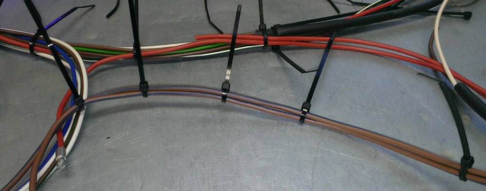
and tested before finally tying everything to the frame. The harness is wrapped with vinyl harness wrap. It is not tape
- no adhesive so it won't get sticky later. You wrap it overlapping the previous wrap by about half and pulling
snug. In a couple of areas where rubbing can occur, the vinyl wrapped harness is inside PVC sleeving. Notice how clean
it is under the tank.
July 13, 2018 The harness is in the bike to stay and the circuits are tested. The tail light is finally installed. The handlebar
consoles are tested and mostly don't work. As you can see, they are currently ugly! So, that's the job
for tomorrow - make them look almost new and work.
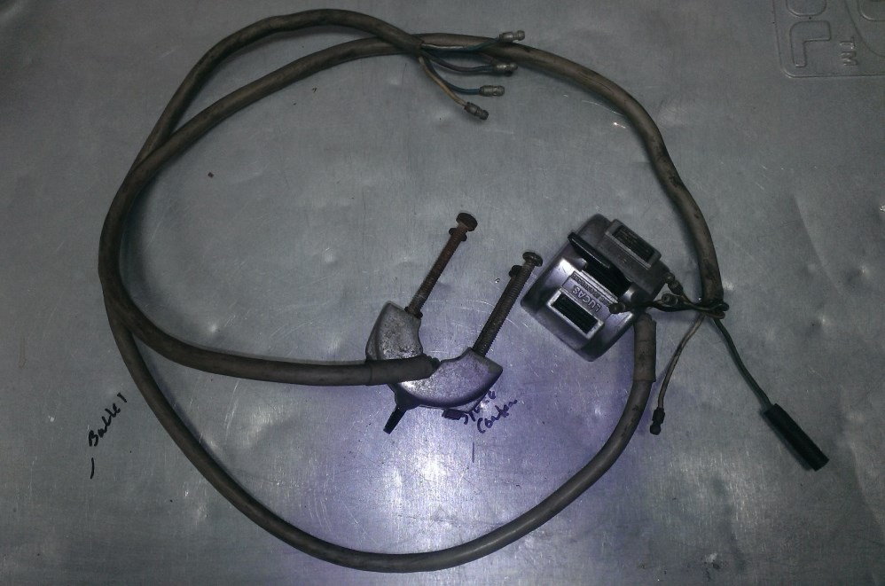
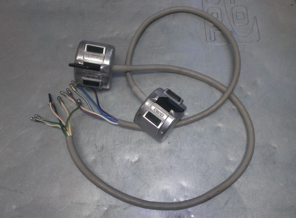
July 14, 2018 To restore the handlebar console housings I follow this procedure:
- Take them apart. Often, it's hard to get the screws out. One came apart easily, and the other was a bear because the
last guy stripped the screws. Fortunately, I have replacements. BTW, these required 4/40-5/16. The newer
ones take #4 sheet metal screws. The newer ones are those with Lucas twice on the front.
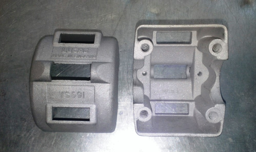
- Media blast them at 45psi. That works best with glass beads, but I had glass abrasive loaded so I used that.
It's fine but takes a little longer to polish.
- Buff them on my buffer, first with brown compound and then white.
- Clean them with WD40 and a soft brass brush and then with soap and water.
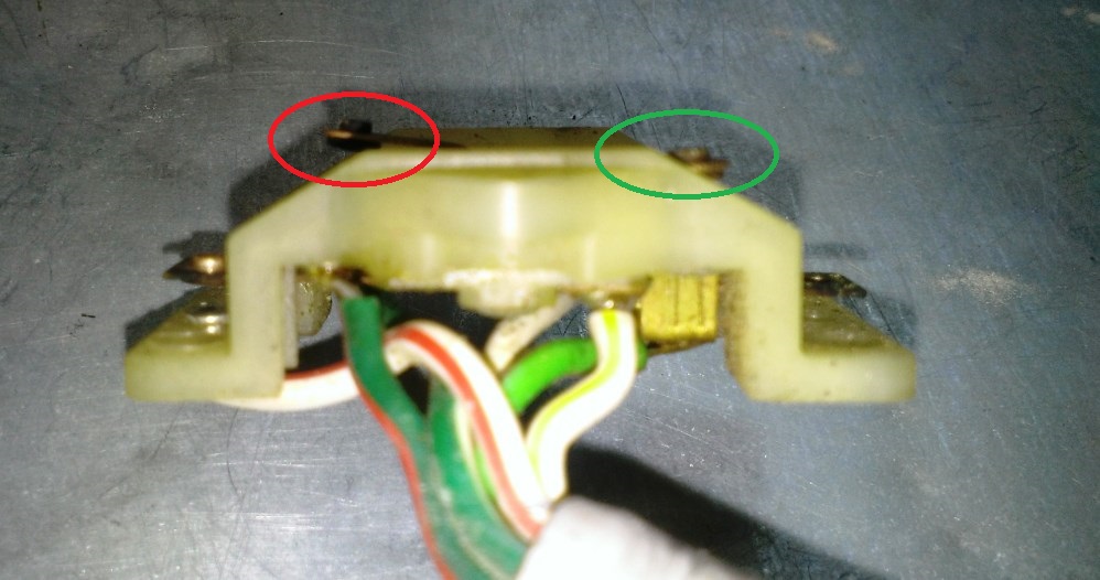
Then I test/fix the wiring and contacts. Notice the green and red circle in the second picture. The contact
in the red circle touches the housing - really not good. I've seen this many times. You have to carefully
reform it and it will be fine. I test every wire for short circuits and for resistance. The bullets on these
were crimped but a couple would move on the wire. Several circuits have 1-3 ohms of resistance even after cleaning
the contacts. So, I replaced all the bullets - crimped and soldered. Then all circuits tested zero ohms.
Think about how important that is: The White/Yellow to White wire was 3 ohms and with the contact cleaned 2 ohms.
The White wire bullet was causing that. The coils are fed from the White/Yellow wire. With electronic ignition
and 6volt coils wired in series, they are about 3.2 ohms. I=E/R so I (amps) should be about 12.8/3.2=4 amps.
With the bad connections, 12.8/6.2=2 amps. Two amps for the coils is not good!
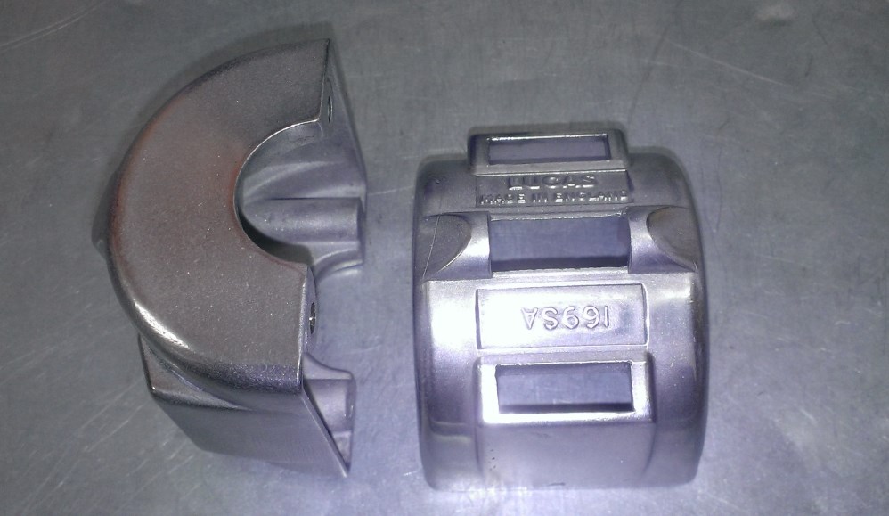
The last picture shows the consoles ready to install
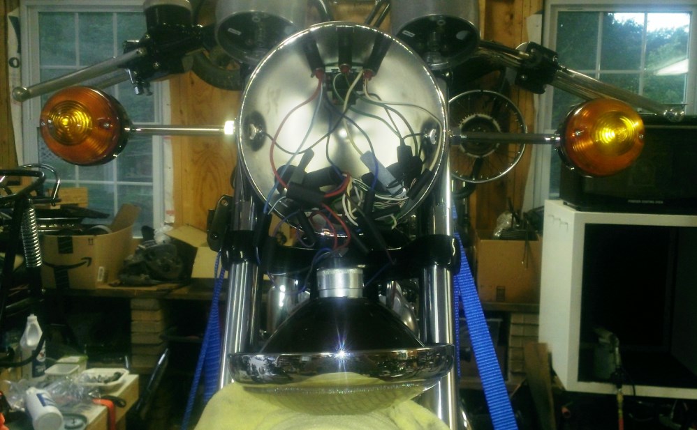
July 19, 2018 The wiring is done and tested except the front brake switch and the instrument lights. The headlight now looks
like a Triumph rats nest but at least there are no extra connections under the tank, or anywhere for that matter. Once I
add the brake and instrument lights, I'll dress the wires in the headlight so they are out of the way of the beam unit
and it will all be done.
|