|
|
 | Sunday, July 26, 2026 |
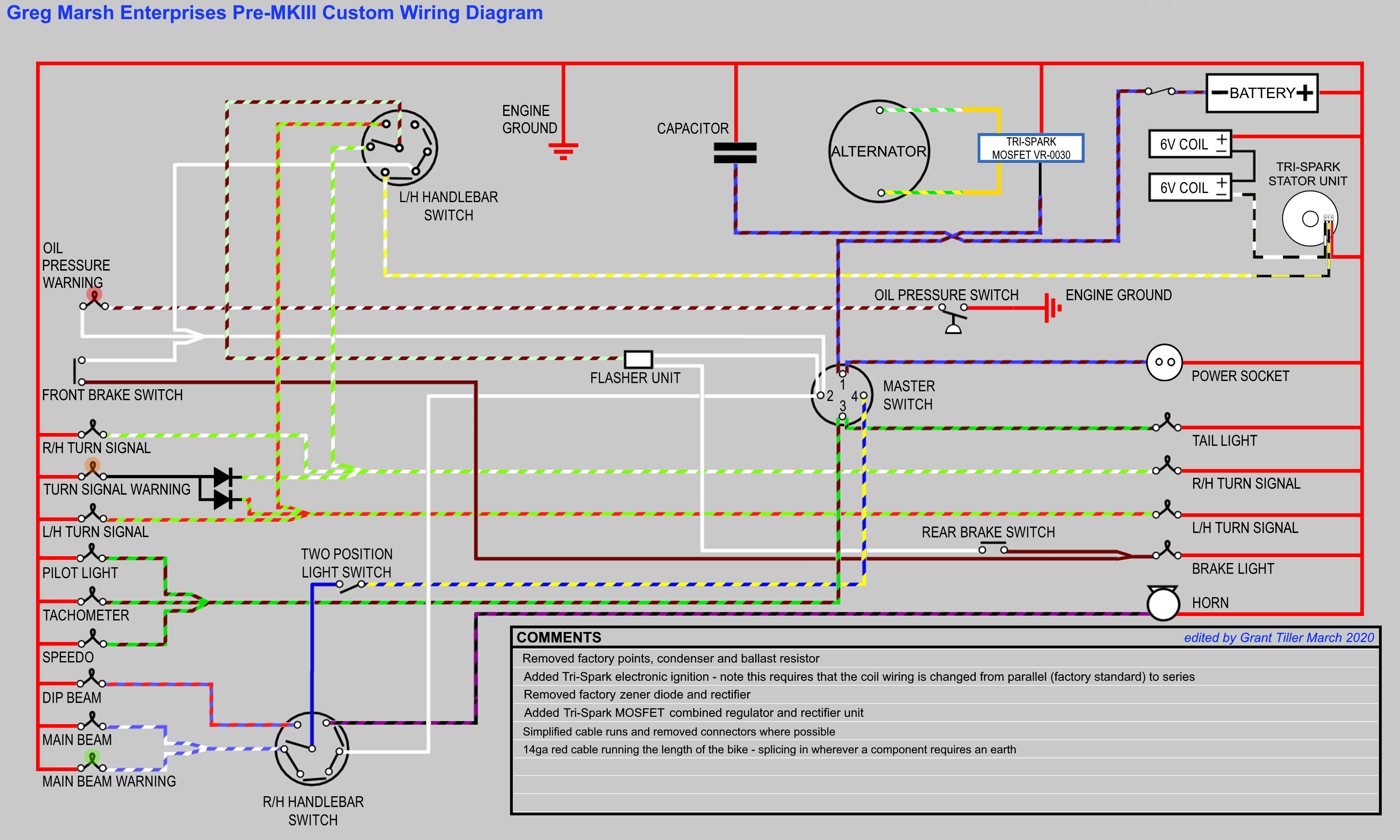
I've already detailed the wiring of a 1972 and a 1974 Commando from scratch but until now, I didn't have a wiring diagram to match how I do them. The diagram below is for all pre-MKIII Norton Commandos. Since there are some subtle differences, for instance the taillight used, some notes are required that don't fit on the drawing. Also, the drawing shows the grounding (earthing) as it is electrically, but a few notes are required. I'm happy to answer and questions - just all or write.
- For the later (rectangular) taillight, I ground the turn signal stems using eyelets at the mounting point - see the two taillight pictures
here. For the older taillight, I add a ground wire to the turn signals themselves - see the first picture
here. Either method will work for either taillight.
- Since the headlight is held to the fork ears on a Norton but the turn signal stems, I ground the headlight shell which grounds the turn signals.
- If you want to use LEDs for the indicators, speedo/tach illumination/pilot light, it's not a problem but since the bikes is wired positive ground the connections to the indicators must be reversed. If using the current Lucas indicators, this is not a problem since they have spade terminals. If using the original sockets, then the wire colors will be wrong, but they must be swapped. Unfortunately, the new Lucas indicators are a problem because they interfere with the back of the beam unit. With careful bending of the terminals, you can get them to work - but just. This is true whether normal bulbs or LEDs. I'm working on a solution for this, but it's not ready yet.
- If you use a standard bulb for the turn signal indicator (amber), you can use the diodes shown, but the standard wiring will work fine. The diodes are required when you use an LED for the indicator. Look almost at the end here for more information.
- Note that Norton swapped the left and right handlebar switches during 1972. I find it silly to have the turn
signal control on the right so I show it on the left as it was on the earlier bikes and on my Triumphs. The wiring
doesn't change to swap sides, you simply swap the wired consoles.
A member of the Access Norton Forum, Grant Tiller, has been making colored Norton wiring diagrams for some time now. He has kindly made a custom diagram to match the way I wire them. To see his other diagrams, look here.
|