|
|
Introduction
Note: I'm writing part of this, especially the last part, before actually doing it on this bike so I may change things as I go. I don't need a document to do this so the only way I can be sure the document is right is to write it and then do it! Finally, this is not finished but I've spent over 40 hours on it and will finish it!
This document tries to cover wiring a stock Norton Commando, a stock Norton Commando with the Colorado Norton Works (cNw) e-start, and the Norton Commando 850 MK3 using my methods. I will try to explain where there are differences in them. The Commandos with ammeters are not covered but you can call me if you need help with them. Mostly this will work for them as well, but the main battery negative wiring and the location of the master switch and the master switch type are radically different.
- Tri-Spark VR-0030 MOSFET Voltage Regulator. Depending on the air filter, the regulator can be mounted in various locations so the instructions will be somewhat vague on its wiring.
- Tri-Spark Tri-0006 ignition system.
- No connector block under the tank - most connections in the headlight shell.
- No bullets - WAGO connectors instead.
- Positive Ground
- Correct wire colors
- Correct wire but see the next section that explains what that is.
Throughout this document:
- You will see the term "breakout". This means where a wire (or wires) leaves the main harness and goes somewhere.
- You will see references to "Combat5". It is a 1972 Combat with the cNw electric starter and air filter. It is being wired and documented here, see: Fifth Customer Combat - GME. I either use its pictures or refer you to a date or date range in that page often.
- The MK3 is quite a bit different than all others in that there is a console with warning lights and the master key. I mention the differences but until I wire the next bike I'll build (it's an MK3), I can't be very specific here. However, while not overly specific, this is how I wire a MK3: Custom Wiring a 1975 Norton Commando for Reliability - GME. For now, it's better to at least refer there for the MK3 info.
If you would like to print this, click here and then right click on the new tab and select print.
Things you Need
Correct Wire
Originally, most British bikes were wired with all "14 strand" wire. That literally means flexible multi-strand wire with 14 individual copper strands; it was a British standard. It is equivalent to AWG 18 gauge, and it is able to carry 8 amps.
I buy my wire from: https://www.britishwiring.com/default.asp. They have several wire types. The PVC wire is nearly identical to the original. They have all the correct colors.
One pitfall with the original wiring is that the ground and Brown/Blue from the battery to the Master Switch were 14-strand. That meant that the wires were nearly fully loaded with the lights on and the engine running. Turn on the turn signals and push the horn button and more than 8 amps was flowing through them - not good!
I use 28-strand for the main ground wire and for the Brown/Blue wire. Also, I use three 14-strand white wires from the master switch. White wires are the "hot" wires. I use one for the left handlebar console, one for the right, and one for the other things that need -12 volts.
I do all this so there is never an overloaded wire anywhere in the bike.
The 28-strand wire is equivalent to 14 gauge AWG.
Because I happen to have a 100' spool of 14 gauge red wire and a 100' spool of 18 gauge red wire, I use that instead of the 28-strand and 18-strand red wires, but you can't tell the difference looking at them.
Zip Ties
I use LOTS of 4" zip ties - buy a bunch at once so you are not nickel and diming yourself! On Amazon the 1000 pack of 4" costs about $8 which is less than a penny each. If you are wiring one bike, then buy at least 200 or if you're really cheap, live with 100. On Amazon a 100 pack costs $2 less than the 1000 pack I buy but then the ties are 6 cents each!
Sleeving
I use sleeving on all wires outside the main harness and on the wires to the taillight. I have every size that Amazon sells of PVC sleeving but you do not need all sizes. Just make sure to get the "uxcell Black PVC Tube Wire Harness Tubing". As of this writing, all sizes are available here: https://a.co/d/03Dxl8Um. You need:
- 3mm Good for a single 14-strand or 28-strand wire
- 4mm It is possible to put two 14-strand wires through but difficult. Fine for one 28-strand but I prefer 3mm for that.
- 5mm Easy to put two 14-strand wires through. Fine for one 28-strand but I prefer 3mm for that. Would work for two 28-strand but that is not needed in my system.
- 8mm Good for four 14-strand and one 28-strand. Use this for the wires to the taillight.
- 12mm, 14mm, or 16mm You need about 14-15" for the harness where it goes around the steering head. 12mm will just barely work, 14mm is optimal and 16mm will work fine.
You could use heat shrink tubing instead of sleeving, but I don't recommend it. The sleeving is flexible, UV safe, gloss black, tough and made for harnesses.
Harness Wrap
This looks like electrical tape but has no adhesive and it is meant for wrapping automotive harnesses. I prefer this one from British Wiring: "Harness Tape, 3/4" Wide - Black (C453)" but the similar ones that Amazon sells are fine too. I find the 1" wide version harder to wrap nicely so I stick with the 3/4" wide. NEVER use electrical tape - it makes a gooey mess over time!
Test Leads
These are not absolutely required but I find them handy. I use these: https://a.co/d/0dwG4yPQ
WAGO Connectors
WAGO is a German company that makes lever lock connectors. They work for all wire sizes used here and many more. They cost less than bullets and in most cases that much less space. They have four types. I'll count how many I use and list it here later - the numbers listed are from memory.
| Part |
Description |
Needed |
| WAGO 221-412 |
Two Connection Lever Lock |
~15
|
| WAGO 221-413 |
Three Connection Lever Lock |
~5
|
| WAGO 221-415 |
Five Connection Lever Lock |
~5
|
| WAGO 221-2401 |
Inline Two Connection Lever Lock |
4-5
|
Other Connectors/Components
These are all from British Wiring
| Part |
Description |
Qty
|
For |
| C135 |
35 amp Glass Fuse |
x
|
These are the correct British (Lucas) Rating fuses 17/35 amps. |
| C141 |
Inline Fuse Holder |
1
|
Standard Fuse Holder
|
| C221 |
1/4" Spade Connector |
7
|
Master Switch & Flasher
|
| C252 |
3/16" Ring Terminal |
6
|
Battery Terminals and coils. Some battery terminals will require C253. The hole in these is not consistent, they might require reaming.
|
| C254 |
5/16" Ring Terminal |
1
|
Head Ground
|
You can use standard bullets - British Wiring has all you need. However, they are expensive, a PITA, and I no longer use them.
Amazon has several kits of WAGO connectors plus individual connectors. I buy them in large quantities so I can probably save you a little money if you get them form me.
More on Fuses
The various manuals for British bikes and cars often specify 35 amp fuses. They are British (Lucas) Standard fuses and are really 17/35 amp and are quick blow. The most common US fuses are AGC. An AGC 35amp fuse will not blow before your wring melts! The larges AGC fuse you should use is AGC-17. Also available are SFE fuses. Of them, only SFE-20 is the right length for the fuse holder but they blow faster than AGC so 20amp is barely OK. Since most of the wiring can withstand 8amps for long periods, an AGC-10 or AGC-15 would normally be OK. I use AGC-5 or AGC-10 while testing, preferring if I can find them AGC-5.
Meter
You need a voltmeter and an ohmmeter (multimeter has both). I DO NOT like digital for any sort of automotive work! An inexpensive analog meter is much better. In fact, my favorite meter came from Radio Shack years ago for $3.00. The voltmeter needs a range for reading battery voltage - 15 volts DC is good but many have 2.5, 5, 10, and 50 and more. The 50 range will work fine it's just harder to get a exact reading. The Ohmmeter portion must have a x1 range and it's nice if it makes a noise when connected. Checking today, the best option I see on Amazon is: https://a.co/d/00ZoVWox. If you already have a digital meter, it's fine for static wiring testing like you'll do here, they just are not good for running bikes - too much electrical noise.
Dielectric Grease
This is not strictly required but I very lightly coat all non-soldered bare wires with it. I use: https://a.co/d/0hOF7Ql7
Touching bare wires with your fingers almost ensures corrosion in the future. You could clean the wire with denatured alcohol before connecting, but the grease is better protection. Of course, you're preventing something way down the road and with WAGO connectors the connection is air tight so there will be no corrosion if never re-opened and closed.
Getting Started
Handlebar Consoles
Near the end of wiring, you'll need working handlebar consoles. If you don't know how to test/fix/renew them, it would be best to send them to me. They must have decent original cables attached (dirty/ugly is OK). I will restore them. If I need a kit of replacement parts for each (usually don't) the pair will cost $220 delivered looking good. If no kits are required, then $160 delivered. If you happen to have extra consoles with decent original cables I will take off $40 for each you send.
General Information
Notes:- If you have a 1971 or 1972 Commando with the Lucas 679 taillight (which is standard), these instructions are correct but this is the last bike I'm doing this way! At the very end, I've described a better way. Read that before running these wires if you want to make it easier!
- If you have the Lucas 917 taillight that was standard from 1973 onward, these instructions correct and how I will continue doing it.
To start you need several wires from the headlight shell to the taillight area. Unless otherwise noted, all wires in this document are 14-strand PVC coated.
- Cut but don't run yet one Red 28-strand wire
- Cut but don't run yet one Brown wire
- Cut but don't run yet one Brown/Green wire
- If you will be using turn signals:
- Cut but don't run yet one Green/White wire
- Cut but don't run yet one Green/Red wire
These are all 81" long. Yes, throughout, all wires are longer than they need to be, but there is nothing worse than doing the final wiring and having one or more wires too short!
The red wire will have several red wires spliced to it. For most other wires you can choose to splice or connect in the headlight shell. Generally, I splice. Where I splice, I tell you how to not splice except for the red wires and the Brown/Blue wires. If you don't want to splice these, you're on your own. 😜
Building the Main Ground Wire
All measurements in this section are measured from the end of the red wire in the taillight area.
The back of the rear frame grommet will be at 31". I put three crisscrossed zip ties there to stop confusion later.
These splices must be done and insulated in order! When I splice, I strip the loose wire a bit longer than the part of the main wire I strip. I use an X-ACTO knife to strip the main wire. I then tightly wrap the wires together with clean hands and then solder with rosin core solder - it is imperative that you not use acid core (plumbers) solder! Although it is not needed, I clean the splice after soldering with denatured alcohol to remove any rosin. I then use a piece of heat shrink slightly longer than the splice, shrink it, and then follow with one about 1-1/4" long centered over the splice. Double heat shrink is the kind of overkill that costs very little and greatly improves the chance of long-term success.
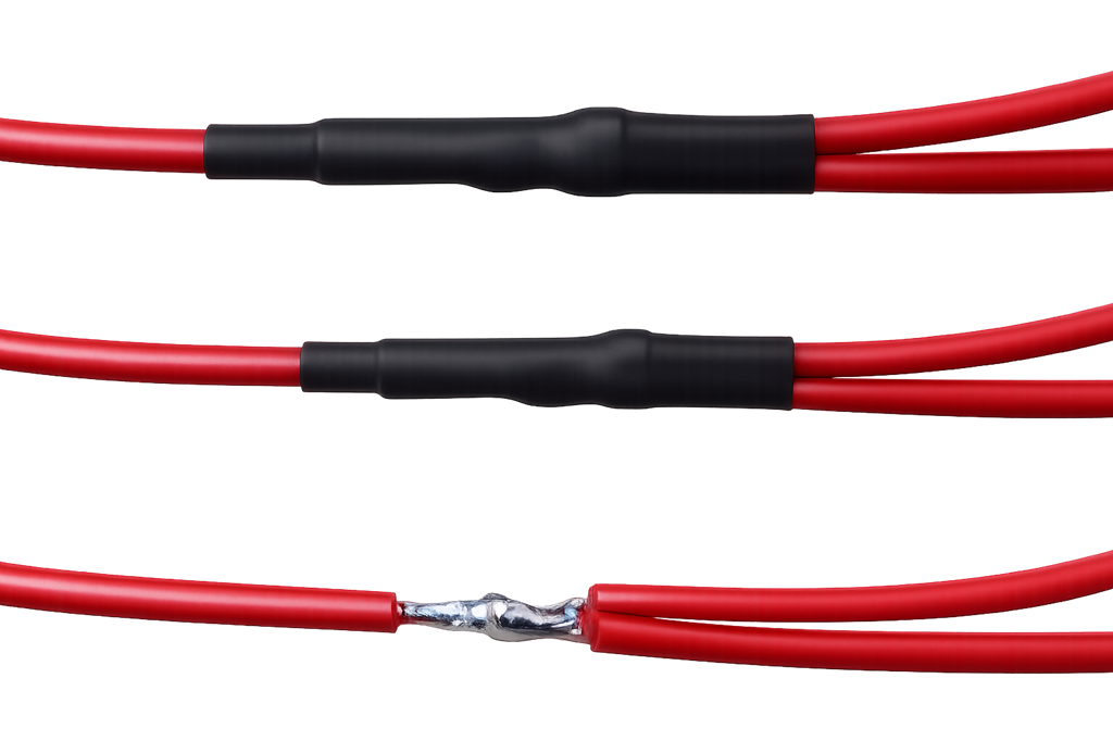
Splice a 27" 14-strand red wire to the main red wire centered at 40.5". This will be the horn ground. This wire exits the splice to the rear.
NOTE: this length and location are for the horns I use mounted where I mount them. If you use the original location or a different location or horn type, you must figure it out! Later, I'll add a picture of my horn mounting.
Splice a 27" 28-strand red wire to the main red wire centered at 42-1/4". This will be the battery + wire. This wire exits the splice to the rear.
There will be a bundle of wires that exit the harness header that go to the master switch. Nominally the center of the breakout to the master switch is at 45-3/4" from the taillight red wire. You'll have to decide the exact location for yourself, but it should be somewhere between 45" and 46-1/2". Just don't interfere with the front frame grommet and be sure it can route nicely to the Master Switch. The MK1A, MK2A, and MK3 require particular attention if using the plastic air box. If using the cNw air cleaner, no telling where or how you will decide to mount the Master Switch and if using the "Hamcan" you might have the regulator mounted to the back of it so again this routing has to be up to you and well thought out! I put 4 zip ties there, side by side, and a sharpie mark on each side of the four on the main red wire as a reminder where that will be. The location of that breakout is one thing that must be right; most other things can vary some. You can look at June 6, 2026 through June 7, 2026 to see where the master switch got mounted on "Combat 5" which is a 1972 Combat getting a cNw e-start: Fifth Customer Combat - GME
Splice an 11" 28-strand red wire to the main wire centered at 53-1/2". This will be the head ground. It is not actually needed for an MK3 or a bike with the cNw e-start, but I use it anyway. The wire exits the splice to the front. BTW, officially the wire connects to one of the studs through the head steady - don't do that. Still use a ring connector and put it under the timing side Allen screw that connects the head steady to the head. If you use one of the aftermarket fancy head steadies (I never do), you'll have to figure that out for yourself. The point is to have a solid engine ground since the Commando engine is rubber mounted.
Splice a 14" 14-strand red wire to the main wire centered at 59-1/2". This will be the coil ground. This wire exits the splice to the front.
Building the Brown/Blue Wire.
This wire connects connection 1 of the Master Switch to the minus of the battery via the fuse. I use the standard fuse holder, and it takes a bit of skill and patience to clamp and solder the connectors on the wire.
I don't install the fuse holder until I'm positive where I want it and the wiring is in place; the wiring does not need to be finished, it just needs the location locked down and the battery sitting where it will go. Note that the plus and minus of the battery can be on either side depending on what battery you bought. Also, the size of the battery varies. I use 9ah AGM (e.g., YB9A-A or YB9A-B) batteries if not electric start and Shorai LFX 18A1-BS12 for electric start bikes and they are MUCH smaller than the AGM batteries.
Cut a length of Brown/Blue 28-strand wire 41" long and mark one end of it. Note: the MK3 will be different! Also, if the Master Switch is very far from the normal location, this wire might need to be longer at the Master Switch end.
Cut a length of Brown/Blue 28-strand wire 7" long.
Splice the short Brown/Blue wire to the long one with the splice centered 17" from the marked end of the long wire. The short wire exits the splice to the rear from the marked end of the long wire. The free end of the short wire will eventually connect to the black wire for the Tri-Spark regulator. If the regulator will be mounted in front of the splice, then the wire needs to leave the splice toward the other end so figure out the regulator mounting before making this wire. Some people use the Andover Norton PODtronics mount (13.1667 or 13.1667/B) and some mount to one of the Z-plates so be sure the short wire is long enough - it should be in all these scenarios as the regulator's red and black wires are long - but check - PITA to fix later.
Zip tie the Brown/Blue and Red wires together using the Master Switch breakout you marked on the red wires. Just make it snug and put another zip tie further back to keep the Brown/Blue in place.
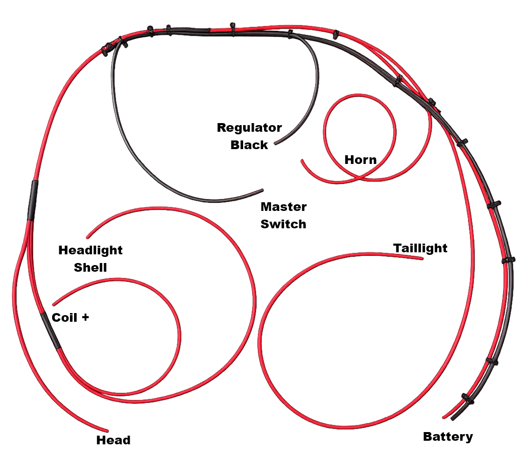
Master Switch Wires
I don't know your master switch location, so you'll have to think this through. If you happen to be working on a 1972 Combat with the cNw starter, cNw air filter and my Master Switch Bracket installed like I have on Combat5 then these instructions are correct. If wiring a MK3 the Master Switch is in the black console so the wire from the battery negative goes to the headlight shell - see the MK3 wiring page I mentioned in the introduction.
The White Wires
Cut three White wires that reach from the Master Switch to the headlight shell. Make sure the headlight end has at least 4" past the front of the shell and that the Master Switch end is through the bracket at least 2" past the end of the bracket with the wires routed along the frame nicely. Now, mark each wire:
- One with one mark on both ends. This will be for the left-hand handlebar console.
- One with two marks on both ends. This will be for the right-hand handlebar console.
- One with three marks on both ends. This will be for the things that are not part of the handlebar console circuits (brake light, flasher).
- When you actually wire the Master Switch, the first two wires will be in one spade connector and the other will be in a second spade connector.
Building the Brown and Three-Mark White Wires.
The Brown wire is for the brake light, and the one you've cut goes from the headlight shell to the taillight. On Combat5, I used the mixed option. Options:
- Spliced
- Run a White wire leaving excess from the rear brake switch along the Brown wire to some point of your choosing through the rear grommet to some location between the front grommet and head steady rubbers. Splice this wire to the White wire between the Master Switch and headlight shell. I used a 57" wire spliced to the White wire with three marks with the splice centered at 19" from the Master Switch end of the wire. The splice exits to the rear.
- If you put the flasher on the back of the frame cross member as is standard for pre-MK3, run a White wire leaving excess from the flasher along the White wire to the rear brake switch. It can be spliced to that wire as long as it goes forward of the rear grommet and can be forward of the front grommet. Splice this wire to the White wire between the Master Switch and headlight shell or rear brake White wire.
- Non-Spliced:
- Run a Brown wire leaving excess from the rear brake switch to the headlight shell.
- Run a White wire leaving excess from the rear brake switch along the Brown wire to the headlight shell.
- If you put the flasher on the back of the frame cross member as is standard for pre-MK3, run a White wire leaving excess from the flasher along the White wire to the headlight shell.
- Mixed:
- Run a White wire leaving excess from the rear brake switch along the Brown wire to some point of your choosing through the rear grommet to some location between the front grommet and head steady rubbers. Splice this wire to the White wire between the Master Switch and headlight shell. I used a 57" wire spliced to the White wire with three marks with the splice centered at 19" from the Master Switch end of the wire. The splice exits to the rear.
- If you put the flasher on the back of the frame cross member as is standard for pre-MK3, run an 18" White wire from the flasher area along the White wire to the rear brake switch to the headlight shell. Splice this wire centered at 45" from the end of the White wire to the rear brake switch.
- Run a Brown wire leaving excess from the rear brake switch to the headlight shell.
- I put the Brown and White wires to the rear brake switch in a 36" piece of sleeving. There are starting to be a lot of loose wires and the sleeving makes it clear where they are going.
- I generally splice the White wires and not the Brown. The Brown already must have a WAGO connector in the headlight shell to connect the front brake switch, so using a 3-connection WAGO takes very little more space than a 2-connector WAGO connector. The White wires cause adding a 5-connector WAGO that otherwise is not needed in the headlight shell and adds three connections - I try my best to minimize connections!
Building the Brown/Green Wire.
The Brown/Green wire is for the lighting and especially the taillight. It goes from the taillight to the headlight shell and also to the Master Switch. Options:
- Spliced: Run a Brown/Green wire from the Master Switch through the front frame grommet and splice to the Brown/Green wire from the taillight to the headlight. On Combat5, this wire is 20" long and the splice is centered at 49" from the end of the taillight wires. This wire exits the splice to the rear.
- Non-Spliced: Run a Brown/Green wire from the Master Switch through the front frame grommet to the headlight shell. Later the two Brown/Green wires run so far will be connected with the other Brown/Green wires in the headlight shell.
- I generally splice the White and Brown/Green wires and not the Brown. The Brown already must have a WAGO connector in the headlight shell to connect the front brake switch, so using a 3-connection WAGO takes very little more space than a 2-connector WAGO connector. There are a bunch of Brown/Green wires to connect in the headlight shell, so splicing reduces them by one. The White wires cause adding a 3-connector WAGO that otherwise is not needed in the headlight shell and adds three connections - I try my best to minimize connections!
Running the Wires
The Main Wires
Route the:
- Made-up Red and Brown/Blue wires through the front and rear grommets.
- The made-up Brown, Brown/Green, and third White wires.
- The other two or four wires you cut before (Brown, Brown/Green, Green/White, and Green/Red).
- The two White wires with one and two marks.
Match up the ends of the wires at the taillight and put a zip tie on them and put a couple more forward of that so the wires are nicely run together. Then attach them to the frame along the timing side. I use a roll of Velcro cut to lengths I need for this. Also run the spliced, non-spliced, or mixed White and Brown wires you made up.
This is the time to make very sure you are happy with the location of all wires so make sure they are routed and secured completely together and to the frame, but not secured permanently.
It is also the time to figure out where the various wires in the battery area will break out from the main harness. I put two zip ties at each of these locations so I can keep track of them. Once all wires are run you will have to remove the entire harness and add sleeving (preferred) or heat shrink to certain areas and then wrap the harness, so you need to know where the breakouts are!
As you add wires, zip tie them to the routed main harness and make sure you use enough zip ties so you're not confused when you take the harness off the frame for the next steps. Also make sure the harness is routed nicely as you install zip ties and they will cause the harness to somewhat hold a shape.
The Rest of the Harness Wires
I mostly don't give lengths in this section. Just make sure the headlight shell ends match up with the wires already run and tie each wire to the main harness as it runs. I usually cut the old zip ties and add new when running each wire.
- If using the Don Pender oil pressure switch, it mounts to the rocker feed line at the bottom of the timing cover. A White/Brown wire is needed for it to the headlight shell. Where it is outside the main harness, I put it in a piece of 3mm sleeving, and it breaks out of the harness about 1" before the front of the front frame grommet. The sleeved wire then goes through the front frame grommet and follows the timing side frame tube down to the switch.
- Run a Light Green/Brown wire from the headlight shell to the end of the White wire to the flasher as mentioned before.
- Run a Purple/Black wire from the headlight shell to the end of the 14-strand Red wire mentioned earlier for the horns and pay attention to the comments made there!
- Run a Blue/Yellow wire from the Master Switch to the headlight shell. This wire will connect to the switch in the headlight shell. It will be connected to terminal four of the master switch.
- Run a White/Yellow wire from the headlight shell to about 3" in front of the rubber mounts of the head steady. Run this even if you don't plan to use the kill button - I'll explain later hat to do in that case.
- If wiring a MK3 you need a White/Red wire from the headlight shell to the starter solenoid. If wiring a cNw electric starter, you must decide whether to follow their instructions and route their long wire. I don't do that. I run a White/Red wire from the headlight shell to near the flasher and I connect their starter wire to that.
- Zip tie all the wires together. I go along cutting zip ties that are on less than all of the wires and adding new around all wires.
- The Tri-Spark ignition needs two wires - a Black/White and a Black/Yellow.
These don't have to be prepared right now, but I put them here so the coil and White/Yellow wiring will make sense.
- If you have two coils, the Red 14-strand wire from the harness will connect to the plus on one coil and there must be a jumper from the minus of that coil to the plus of the other coil. If you have a single coil, the Red 14-strand wire from the harness still connects to the plus (if marked) on the coil.
- I put the Black/White and Black/Yellow wires in 4mm sleeving (with difficulty) or 5mm sleeving.
- The Black/White wire connects to the minus of the coil where there is no wire.
- The Black/Yellow connects to the White/Yellow from the headlight shell. This White/Yellow is the "hot" side of the kill button and provides the power to the Tri-Spark unit.
- Note: if you don't want to use the kill button still run the White/Yellow but in the headlight shell, connect it to the White wire with three marks instead of the White/Yellow from the handlebar console.
Before moving on, look at the wiring diagram and at each thing that must be connected to be sure there is a wire to connect!
Initial Preparing to Wrap the Harness
I use sleeving on ALL wires leaving the harness. That sleeving extends past the breakout to near the terminal (if any) that connects to something. At this point as long as a little wire is sticking out from the sleeving where it will connect to something and the harness end is at least 1" into the harness past the breakout point you are fine.
At each breakout, zip tie the sleeved wire exactly where you want it to break out and then one more time near the end of the sleeving.
The hardest breakout to handle is the one to the Master Switch since the wires are coming from two directions. You must never kink wires. Copper when kinked eventually becomes "work hardened" and brittle - this is not good. A small radius is fine, just not a kink. In this one place, electrical tape can be used to cover the breakout "V" of the wires and the end of the sleeving so the sleeving cannot slip, but it must be covered with the harness wrap when you finally wrap the harness.
Final Preparing for Wrapping the Harness
There are a few things left to sleeve. These can be done with difficulty using 4mm sleeving but are easy enough with 5mm sleeving:
- The Brown and White wires that go to the rear brake switch need sleeving from the switch to about 3" inside the rear frame cross-member. I normally have already done this as I said before.
- The Light Green/Brown wires to the flasher need sleeving from the flasher to about 3" inside the rear frame cross-member.
- The Purple/Black and Red wires to the horn need sleeving from about 2" from the end of the wires to about 3" inside the rear frame cross-member.
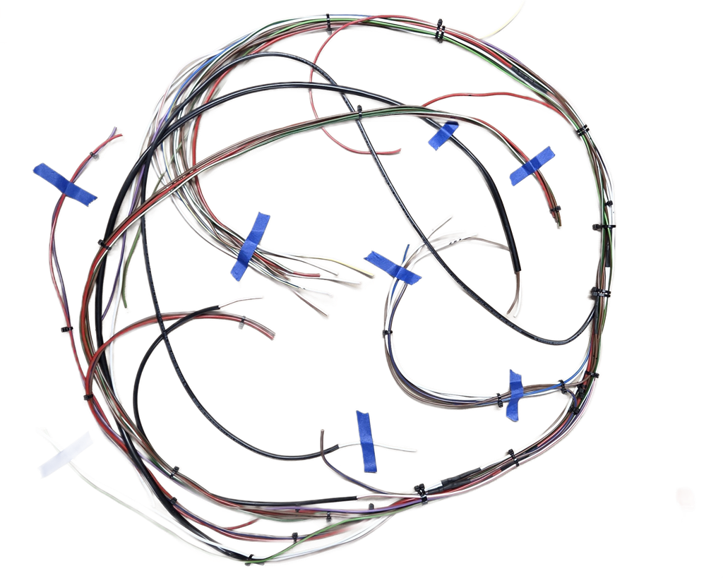
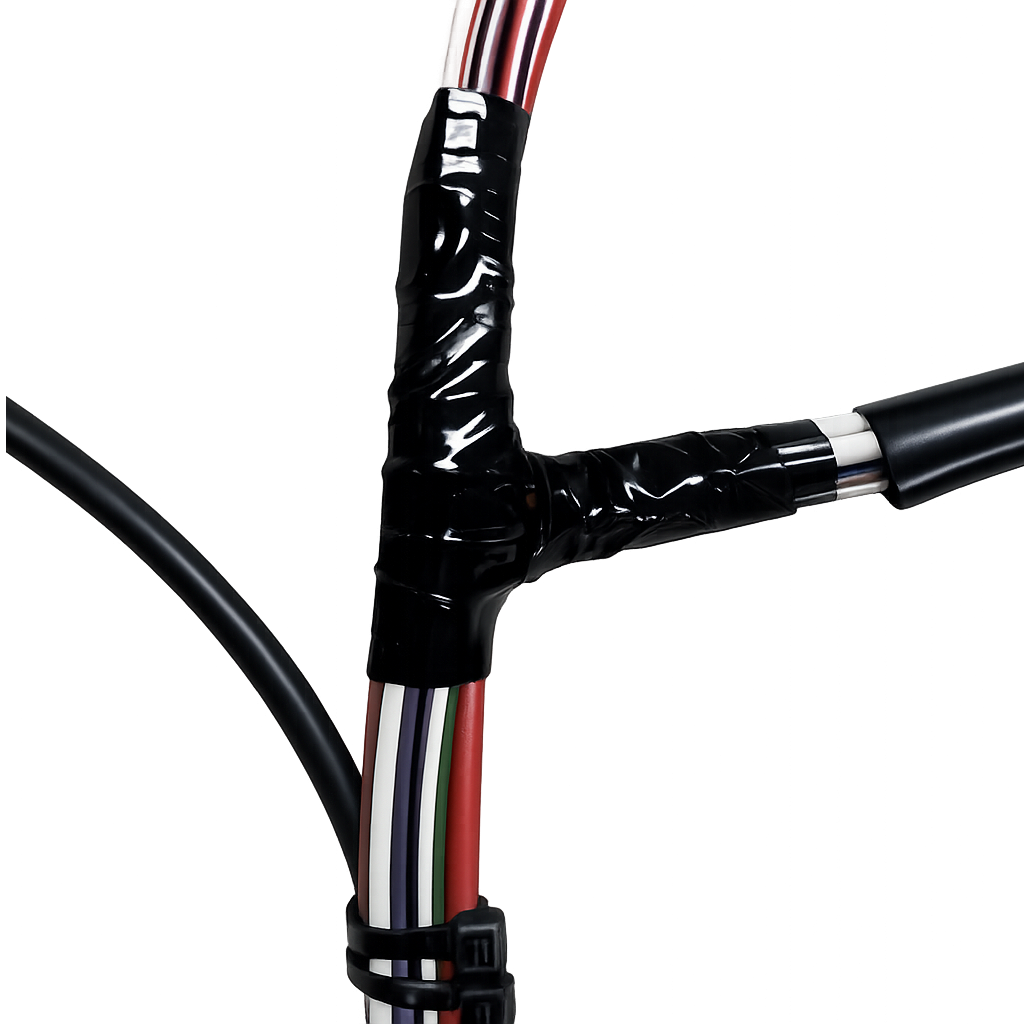
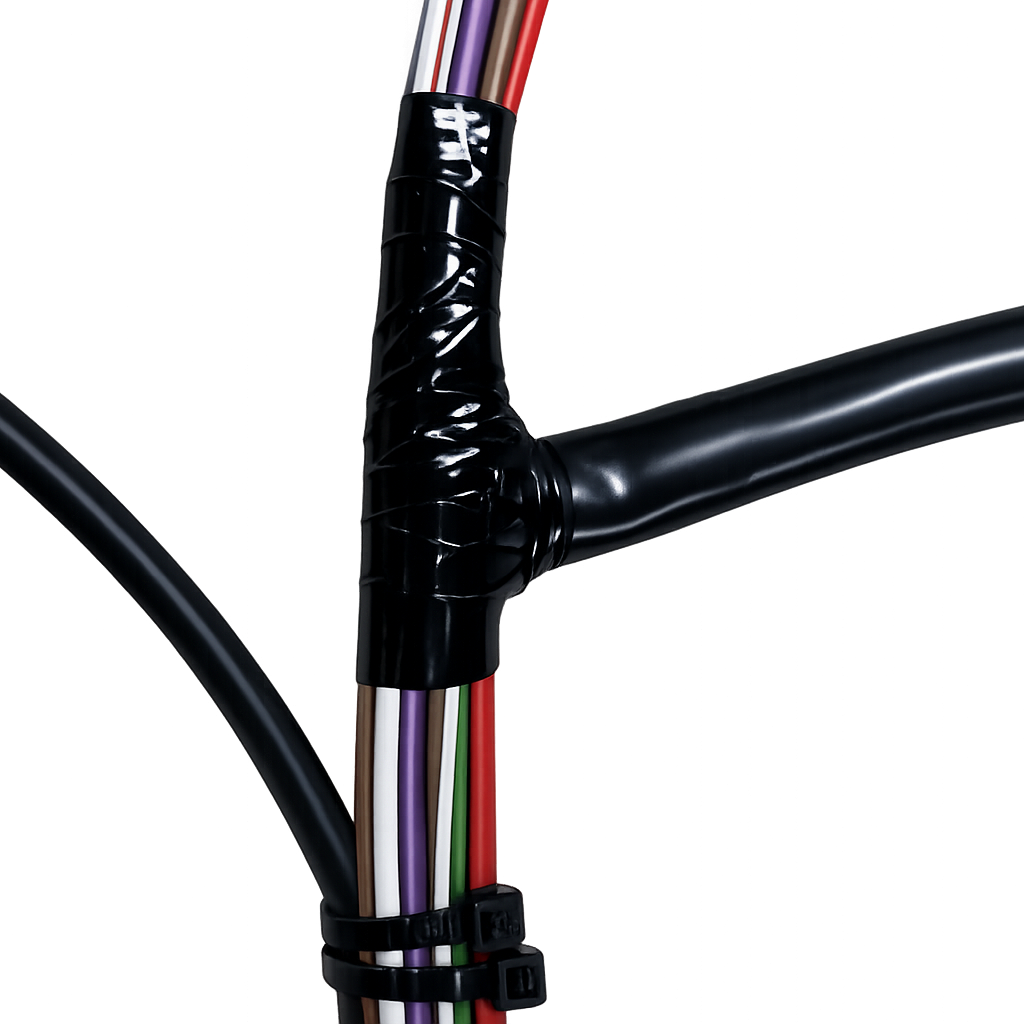
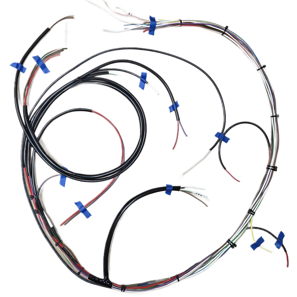
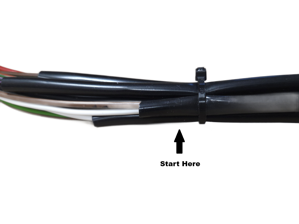
The next four pictures have a long story. The short version: I was using Microsoft's Copilot to clean up the pictures. It did the 2nd and 3rd pictures perfectly (they were the first two I had done in the session). Then Copilot lost all capability to do the work and I spent half the night fighting with it. Finally, I logged onto another computer and it could do it. I gave it the first picture and it did a perfect job, but cropped the top and bottom so I asked it to fix that, which it did, and made the picture ugly and unusable in the process. After more hours fighting that, I bought software to do it which removed the background but could not remove the blue tape and made relatively ugly pictures. Still, they are better than the pictures I took as the harness was taped down to a piece of brown craft paper. I finally gave up and used those pictures.
The point of the pictures:
- First: Show the rat-nest the harness is when together, breakouts marked, and mostly not sleeved.
- Second: The Master Switch breakout is the hardest as it has wires coming from each direction and needs a sleeve as well. My first picture was lost; it showed the breakout with no wrapping. I used harness wrap (no adhesive) and started in the "V" the wires formed and then wrapped as you see. The wrapping will be covered by the final wrap.
- Third: Shows the Master Switch sleeving over the bottom of the Master Switch breakout wrapping. In the final wrapping this all ensures that there are no bare wires in the breakout.
- Fourth: All sleeving installed and all breakouts remarked and checked without putting the harness back on the bike.
The next step:
- Put the harness back on the bike
- Re-check/adjust all breakouts
- Be sure before the next steps that the wires are long enough to reach the battery how it will be installed and if not inline with the bike that there is room to take the battery out and remove the connections
.
- The Brown/Blue and Red wires for the battery are long enough to reach the terminals of any battery mounted any way.
- For the MK1A, MK2A, and MK3 the battery is mounted across the frame so the wires must be long enough to take the battery out with the wires connected to be able to disconnect the wires.
- For the other 1971 and later bikes, the battery is mounted in-line with the bike so the wires don't need to be extra long and can be disconnected with the battery in place.
- In either case, the Brown/Blue and Red should be in sleeving past anywhere that they can rub on something - mark where this sleeving will end.
- Cut the Brown/Blue wire to where the long end of the fuse holder will be terminated, the long end termination will be done with the harness off the bike. The short end is done later.
- Cut the Red wire to the battery positive to length - the ring terminal will be put on with the harness off the bike
- Mount the Master Switch in the bracket.
- Properly routed the wires to the Master Switch cut the wires to the correct length. Since they have to curve in the cover and bunch up as ell, give yourself about 1/4" to 1/2" more than you think you need!
- Look at the wires and rear rubber cover for the Master Switch. The sleeving must go inside the cover but not too far. Refer to picture three below to see where the harness end must end.
- Cut a piece of sleeving the correct length for the Master Switch wires.
- The MK3 rear cover is different from the pre-MK3 in the way that the wires leave the cover. That MK3 cover can be used in certain situations based on where the Master Switch is mounted and on Combat5 it is used for that reason.
- Cut all the wires to the correct length to connect to the Master Switch, keeping in mind that you are connecting to spade terminals and everything must fit inside the cover!
- Take the harness off the bike
Wiring the Master Switch
-
Put the sleeving on the wire and ensure that the harness end is where the third picture above shows.
- Put the cover over the wires and sleeving.
- I use a little Vaseline on the sleeving to make this easier.
- Slide the cover up the sleeving some to get it out of the way.
- Check the back of the Master Switch. If the terminals are not marked, throw it away and buy a proper Lucas Master Switch. The unmarked aftermarket Master Switches are never good!
- As you terminate the wires, you must include a piece of heat shrink that covers the entire spade connector and a small bit of the wire. The wires tend to get pressed together somewhat and you don't want shorts in this!
- Terminating and connecting:
- The Brown/Blue wire gets a crimped, soldered, and heat shrink cover and gets connected to terminal one of the switch.
- The Brown/Green wire gets a crimped, soldered, and heat shrink cover and gets connected to terminal three of the switch.
- The Blue/Yellow wire gets a crimped, soldered, and heat shrink cover and gets connected to terminal four of the switch.
- This leaves three White wires. Put the one with one mark and the one with two marks in one spade terminal, crimp, solder, and cover, and connect to one of the two terminals marked two on the switch. Then crimp, solder, and cover the other White wire and connect it to the other terminal marked two on the switch.
- Slide the cover down over the wires and, while cussing a lot, put it over the back of the switch.
Wiring the Fuse Holder and Battery Ground Wire
Slide the long end of the fuse holder on the wire from the harness followed by the spring and then crimp and solder the connector on the wire. Yes, it looks impossible to get that big wire in that small connector - it's not - I do it every time!
With the piece of Brown/Blue wire you cut off, crimp and solder the other connector, then put the wire through the small end of the fuse holder and install a fuse. I use an AGC 5-amp fuse for testing and later switch to the proper fuse once everything is tested.
Slide a piece of heat shrink on the Red with that will go to the battery Positive, terminate the wire with a ring connector that matches the battery screw (crimp and solder), and then slide the heat shrink into place and shrink it.
Wrap the Harness
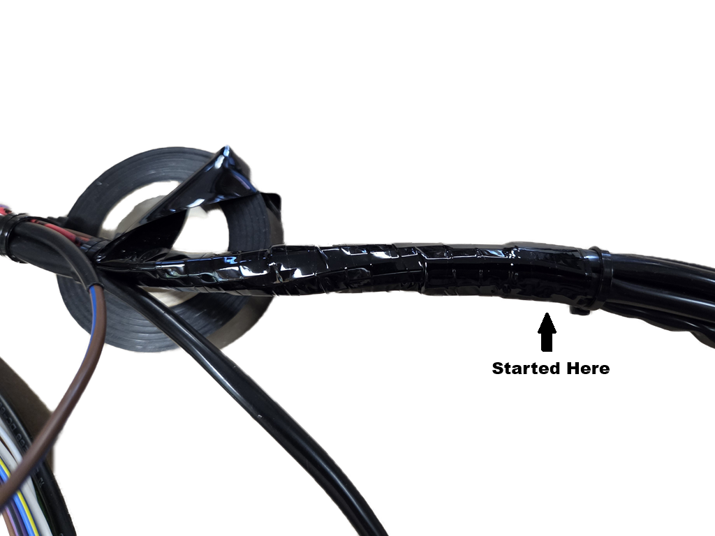
To start wrapping make sure you start about 3/4"-1" before the end of the shortest sleeving that goes through the rear frame grommet. Wrap around straight three times and then start going forward over lapping the last wrap about 1/2. You need to pull taught but not enough to stretch the wrap where it gets narrower and make sure there are no wrinkles. If you don't like something you can unwrap until the problem and the go forward. Keep doing that until you get to the first breakout. Go under the break out as close as possible then over 2-3 wraps and the keep going overlapping 1/2 until the next breakout. Then continue to about 1" before the headstock. In theory, it won't unwrap but I put a piece of tape there. It will be covered by a sleeving that goes around the headstock and into the center grommet of the headlight shell. BTW, when you have a single tie wrap that was just holding the harness together, don't cut it until you get to it - they tend to hold the curves in the harness and the harness wrap will then maintain the curves.
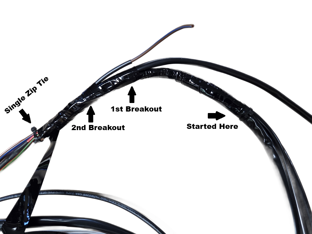
Install the Harness
It is time to (hopefully) install the harness for good. All PITA connection that could be made on the bench have been. Almost all the rest are WAGO connectors so easy so install. Only the flasher, rear brake switch, and horns must be terminated with spade connectors with the harness on the bike.
Preliminary Wiring for Testing
These steps provide the wiring needed for the initial testing. It is best to do this noe so if you discover a mistake it's not as hard to recover as it would be is all wiring were complete.
- Since the Master Switch is all wired and the cover is on, put it in place in the bracket.
- Connect the Red battery wire to the battery.
- Connect the Red head ground wire to the head via the timing side Allen screw for the head steady.
- Finish the Battery Brown/Blue wire but don't connect it to the battery yet.
- If you haven't yet, put the fuse holder contact on the Brown/Blue wire you saved
- Thread the wire through the short end of the fuse holder from the inside out
- Figure out how long to make the wire and cut it.
- Put a piece of sleeving on the wire and slide it all the way to the fuse holder and cut it so that thee is about 1" of wire sticking out.
- Slide a piece of heat shrink over the sleeving and solder the ring connector on.
- Slide the heat shrink into place and shrink it.
- When done, you should have a small area of Brown/Blue wire showing between the heat shrink and the sleeving
- If you did not use the spliced version for the Brown and/or Brown/Green wires. The two Brown (if two) must be connected together in the headlight. Similarly, the two Brown/Green wires (if two) must be connected together in the headlight. Leave these connect until the final headlight shell wiring.
- Look at the free end of every wire other than those in the taillight area and be sure they are not touching anything! The first tests will be without a fuse and not using the Master Switch so you don't want anything shorting out!
Preparing, Connecting, and Testing the Taillight
The taillight and turn signals (if used) need a good ground. The fender is not a good ground! That's the reason there is a Red ground wire to the taillight in my wiring.
Now that the harness is on the bike for good figure out where the sleeving should end to be inside the taillight and rubbing on nothing. The cut the sleeving back to that point. Then wire the taillight and test. If these tests pass, the likelihood is that all your harness is good. If not, oh well, your having fun at least!
Two Types of Commando Taillights
- Lucas 679 (1971-1972) Commandos:
- Has no red wire and is expected to get its ground from the fender - that's fine on Triumph and BSA, does not work on Commandos.
- The turn signals are expected to get their ground from the fender via the mounting bracket. That won't work either and if that bracket is powder coated there is no chance!
- June 6, 2026 here: Combat 5 to see how I prepare the taillight.
- Once prepared, all red wires connect together.
- Do it my way and you never have grounding problems in the taillight area; don't and you likely will!
- This taillight is very hard to wire on a Commando as the taillight fairing is a major part of the mounting. On the later taillight everything is mounted and wired before the fairing goes on.
- Lucas 917 (1973 and later)
- The taillight itself has a red wire but the turn signals do not.
- See July 21, 2019 here: 1974 Norton Wiring to see how I wire this taillight except that I use WAGO connectors rather than bullets today. If you wanted to use bullets you could.
Taillight Testing
Caution: If any test fails from here to the end, do not try the next test. You must fix the problem before moving on. If you can't figure it out, call me!!! Also, if you see more that the tiniest spark while testing there is something wrong - to not keep trying!!!
This testing works whether you used the spliced, non-spliced, or mixed methods for the Brown and Brown/Green wires as long as you've not made any mistakes wiring and have followed the jump instructions given earlier for the non-spliced or mixed methods.
- Connect a test wire to the negative terminal of the battery and make sure the free end does not touch anything other that what is said here and be sure to only momentarily touch things when I say momentarily!.
- Momentarily touch the test wire to the Brown/Green wire(s) in the headlight shell and make sure the taillight filament of the taillight lights.
- Momentarily touch the test wire to the Brown wire that will later be connected the rear brake switch and be sure that brake filament of the taillight lights.
- Momentarily touch the test wire to the Brown wire(s) in the headlight shell and be sure that the brake filament of the taillight lights.
- If you have turn signals, momentarily touch the test wire to the Green/White wire in the headlight shell and be sure that the timing side turn signal lights. If instead of the drive-side lights, you have the Green/White and Green/Red reversed at the taillight - fix that before the next step.
- If you have turn signals, momentarily touch the test wire to the Green/Red wire in the headlight shell and be sure that the drive side turn signal lights.
- Remove the fuse if installed from the fuse holder and connect the Brown/Blue wire to the negative battery terminal.
- Make sure the Master Switch is in the off position (one click clockwise from all the way counter clockwise.
- Put in a fuse no larger that 10 amps, 5 amps preferred..
- Turn the Master Switch all the way counter clockwise and make sure the taillight filament turns on.
- Turn the Master Switch off and make sure that the taillight filament turns off.
- Turn the master switch one click clockwise and be sure no taillight filaments are on.
- Momentarily touch the ends of the Brown and White wires that will go to the rear brake switch and be sure that the brake filament of the taillight turns on
- Momentarily touch the ends of the Brown and each of the white wires, one at a time, in the headlight and be sure that the brake filament of the taillight turns on for each.
- Turn the Master Switch all the way clockwise and make sure that the taillight filament turns on.
- Turn the Master Switch to off.
- Remove the fuse.
If you've made it here there is at least a 90% chance that your wiring harness is correct and ready for final wiring!
Wire and Test the Rest of the Bike
Figure out the routing of the 14-Strand coil ground wire and cut the sleeving and wire to length as before with the hard ground. Do not use a spade terminal - use a ring terminal. Spade terminals corrode over time and it is a hard problem to diagnose! If you have dialectic grease, put a little on both sides of the ring terminal and if the coil contacts are not bright copper/brass, use a brass brush to make them shiny.
If not already done, connect the Black/White wire from the Tri-Spark to the negative terminal of the coil opposite the ones with the Red ground wire. If using a dual coil that has no plus/minus marking, it doesn't matter which gets the Red ground wire and which gets the Black/White wire. The Black/Yellow from the Tri-Spark connects to the free end of the White/Yellow wire coming out of the harness above the coils. If you want to test that wiring now you can by connecting the White/Yellow wire in the headlight shell to any of the three White wires in the headlight shell and following the Tri-Spark test procedure. You'll have to put in a fuse and do the test in the Tri-Spark manual.
Wire all Things not in the Headlight Shell
Rear Brake Switch
- Route the sleeved harness wires to the rear brake switch.
- Figure out where to cut the sleeving and wire ends and prepare them.
- Put female spade terminals and heat shrink on the wires.
- Connect them to the rear brake switch.
- If desired to adjust and test now
- Put the fuse in
- Turn the Master Switch one click clockwise from off
- Adjust the switch, and be sure that the brake light filament comes on properly.
- Turn the Master Switch to off.
- Remove the fuse.
Flasher
- Route the sleeved harness White and Light Green/Brown wires to the flasher
- Figure out where to cut the sleeving and wire ends and prepare them.
- Put female spade terminals and heat shrink on the wires.
- Connect them to flasher.
- This cannot be tested yet.
Horn(s)
- Route the sleeved harness Purple/Black and Red to the ho
- Figure out where to cut the sleeving and wire ends and prepare them.
- If using one horn, put female spade terminals and heat shrink on the wires. If using two, then you will make a harness to go between them and put two Red wires in one female spared terminal and two Purple/Black in the other.
- Connect them to the horn and if using two horns, connect the second one.
- If desired to test now
- Put the fuse in
- Turn the Master Switch one click clockwise from off
- Momentarily touch the Purple/Black wire in the headlight shell to the White wire in the headlight shell with three marks. Make sure the horn(s) honk
- Turn the Master Switch to off.
- Remove the fuse.
Tri-Spark MOSFET Regulator
You have a short free end of a Brown/Blue wire above the battery. Route Black wire from the regulator to that wire, put a piece of sleeving on the Black Wire, prepare the ends of both and use a WAGO inline connector to connect them together.. I use a Velcro strap around the harness, frame and that connector. If not already done, route the Red wire fro the regulator to the positive of the battery, terminate it and connect it to the positive of the battery. This cannot be tested now.
CNW Starter Wire
If you ran a White/Red wire for the cNw starter, connect their starter wire to that White/Red wire. This cannot be tested until all the cNw wiring is complete.
Front Brake Switch
If you already have a harness to the front brake switch, route it into the headlight shell. If not, then you need a Brown and a White in sleeving from the front brake switch to inside the headlight shell. In either case, they can be tested later.
Speedo and Tach Lighting
If you already have a harness to the speedo and tech lighting, route them into the headlight shell. If not, make them up and route them there. They need a Brown/Green and a Red wire each. These will be tested when the headlight shell wiring is done.
Headlight Shell Wiring.
Coming soon!
Alternate Lucas 679 Taillight Wiring
Since this taillight and fairing must go on the bike together, it is difficult to connect the wires to the taillight. Triumph solved this by having a connector under the seat on the drive side near the front of the seat and the wires connected to the taillight with the fairing in-place but Triumph had a frame and therefore rear fender ground so there were less wires to deal with. On a Norton, the wires must go through the rear grommet on the timing side and that prevents using an automotive-type connector as it won't go through the grommet. A 5-way bullet connector could be used or five inline WAGO connectors. Since the WAGO connectors are not black, they would look funny if seen so placement would be important.
The basic idea is to have the five wires that go to the taillight spliced to the taillight wires so the taillight can go on as a unit. The Red wire in this case from the connector back to the taillight can be 14-strand like the other four (two if no turn signals. So, you would splice all the Red wires in the taillight to one Red wire and make that wire long enough to reach wherever you will put the connection. Then do the same with the other wires. The 28-strand Red wire and the other four wires from the harness would end at that same location.
It is best to make these connections in the area just behind the rear grommet. The connection could be done in the battery area but having another breakout there, especially with the 28-strand Red wire involved might be tough. When I wire the next bike this way I will add a picture.
|